Table of Contents
Advertisement
Quick Links
Owner's Manual
VersaTech 1100 ULB+
Do not use this device and its accessories without reading this manual in full.
Illustrations are for information purposes only
.
TECHNICAL ASSISTANCE AND PARTS
1-450-783-6444 1-450-783-6446
info@rotecbeds.com
DOC01E-V11ULB+ REV-4
123 rue de l'Église, Baie-du-Febvre, QC J0G 1A0 Canada
Publication 2022-10-31
Advertisement
Table of Contents

Related Manuals for Rotec VersaTech 1100 ULB+


Summary of Contents for Rotec VersaTech 1100 ULB+
- Page 1 Owner’s Manual VersaTech 1100 ULB+ Do not use this device and its accessories without reading this manual in full. Illustrations are for information purposes only TECHNICAL ASSISTANCE AND PARTS 1-450-783-6444 1-450-783-6446 info@rotecbeds.com DOC01E-V11ULB+ REV-4 123 rue de l’Église, Baie-du-Febvre, QC J0G 1A0 Canada Publication 2022-10-31...
-
Page 2: Table Of Contents
TABLE OF CONTENT GENERAL ......................4 Symbols ........................4 Intended use ......................6 Illustration of the device ..................8 Characteristics .....................9 Optional features ....................9 Intended Accessories ...................9 Mechanical specifications ..................9 Certifications ......................10 Electrical specifications ..................10 1.10 Storage and handling ..................10 1.11 Electromagnetic Compatibility (EMC) ...............11 INSTALLATION .................... - Page 3 Troubleshooting Guide ..................43 WARRANTY AND RETURN POLICY ..............46 Limited warranty....................46 Return policy ......................47 REPAIR PROCEDURES ..................48 Replacing the QLCI (scale circuit)...............48 Replacing the main circuit or its battery ............49 Replacing the VersaDrive battery ..............50 Replacing the power cord ..................52 Replacement of the nurse call port ..............54 Siderail assembly replacement ................55 Replacement of the foot structure extension ...........56...
-
Page 4: General
1.1 GENERAL 1 GENERAL 1.1 Symbols On the device labels Symbol indicating that the mattress dimensions are very important to respect and to consult the user manual to know the characteristics. Symbol illustrating the conditions to respect by the patient to use the bed safely Symbol illustrating the patient's maximum weight allowed on the device. - Page 5 1.1 GENERAL Seal of Approval CSA: Canadian Standards Association Symbol indicating this is a Class I grounded electrical device Symbol indicating that the electrical power must be alternating current. Symbol meaning that the manufacturer or importer affirms the good's conformity with European health, safety, and environmental protection standards European medical device Class I medical device (low risk)
-
Page 6: Intended Use
1.2 GENERAL 1.2 Intended use This manual has been designed to assist you in using the VersaTech 1100 ULB+ bed from Rotec International. Be careful to read this document before using the device to ensure a safe and risk-free usage. - Page 7 Life cycle: This device is designed for a life cycle of 10 years in working condition and in normal use (see the specifications and conditions of use in the following sections) Rotec International cannot be held liable for damage or injury caused by negligence or improper use of its products. Also note that all illustrations contained herein are for guidance only.
-
Page 8: Illustration Of The Device
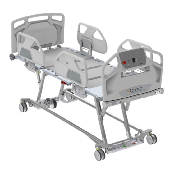
1.3 GENERAL 1.3 Illustration of the device Integrated control in Wall siderails bumpers Siderail Nurse Control Backrest section Versa Auxiliary Drive outlet Seat Section Upper leg section Foot section Brake pedal DOC01E-V11ULB+ REV-4... -
Page 9: Characteristics
1.4 GENERAL 1.4 Characteristics 1.6 Intended Accessories • Mattress, 9 kg (20 lb) ▪ Adjustable height of the bed • Inclinable bed frame (Trendelenburg) • Trapeze bar, 11 kg (23 lb) • Width extension of the platform • IV Pole, 0.5 kg (1 lb) •... -
Page 10: Certifications
1.8 GENERAL 1.8 Certifications 1.9 Electrical specifications Isolation Class I • CAN/CSA-C22.2 No. 60601-1:14 Power 120/220/230/240 VAC • CAN/CSA C22.2 No. 60601-1- Frequency 50/60 Hz Current Rating 120V Model 6:11+AMD1:2015 • CAN/CSA C22.2 No. 60601-2-52:11 + With Outlet: 8.75A With VersaDrive: 4.65 A AMD1:2017 •... -
Page 11: Electromagnetic Compatibility (Emc)
1.11 GENERAL 1.11 Electromagnetic Compatibility (EMC) This hospital bed complies with the following electromagnetic compatibility standards. Test Name Standards Compliance CISPR 11 (2015) A1 (2016) Conducted Emissions Group 1 - class B 150kHz-30MHz CISPR11 (2015) A1 (2016) Radiated Emissions (Prescan 3m) Group 1 - class B 30MHz-1GHz CISPR11 (2015) A1 (2016) Radiated Emissions (10m) Group 1 - class B 30MHz-1GHz... -
Page 12: Installation
2.1 INSTALLATION 2 INSTALLATION 2.1 Powering the device At all times, the primary voltage on the device can be removed safely by unplugging the unit's power cable connected to the wall socket for this purpose. Ensure the power cable is always accessible. Note that this device is of Class I and must be plugged in a grounded outlet. -
Page 13: Verification Before Putting Into Service
Note that the verification of CPR function should be performed with a mattress and a person adequately leaned as it is calibrated to work with the intended patient weight. If damage or malfunction appear on the bed, without hesitation contact the Technical Services Department of Rotec International. WARNINGS ABOUT VERIFICATION ▪... -
Page 14: Positioning In The Operating Environment
2.3 INSTALLATION 2.3 Positioning in the operating environment To install this bed model, place it horizontally at a distance of at least 127 mm (5 inches) from the wall. In the same manner, check that no object obstructs the end of the feet section and then apply the brakes (see section 3.2) 127 mm (5 in) -
Page 15: Installation/Replacement Of The Mattress
2.4 INSTALLATION 2.4 Installation/Replacement of the mattress Use a mattress corresponding to the recommended specifications. Ensure that the platform configuration is matching the mattress. (See Mechanical Specifications) Lay the mattress on the device and insert it in between the rail guards of the platforms. Notice that the mattress must be compressed to be inserted. -
Page 16: Operating Instructions
3.1 OPERATING INSTRUCTIONS OPERATING INSTRUCTIONS Electrical functions of the bed Symbols Descriptions Arrow pointing upwards: Allow upwards adjustment of the various functions of the equipment. Arrow pointing downwards: Allow downwards adjustment of the various functions of the equipment. Backrest functions: Allow tilting adjustment of the backrest section upwards or downwards. - Page 17 3.1 OPERATING INSTRUCTIONS Locking functions: Allow locking a function of the remote control and of the patient control from the nurse control at the foot of the bed. Press this button to lock the function displayed nearby. A red indicator with light up underneath the lock symbol, indicating that the function is locked.
- Page 18 3.1 OPERATING INSTRUCTIONS WARNINGS ABOUT THE USE OF ELECTRICAL FUNCTIONS ▪ If the user's physical condition requires it, and that, for his own safety, lock the movement of the bed functions intended to be used by the patient and place the bed in the low position, the platforms horizontal and bed rails in the raised position;...
-
Page 19: Moving The Device
3.2 OPERATING INSTRUCTIONS 3.2 Moving the device To move the device, it is recommended to raise the bed of at least 150mm (6 inches) from its lowest position to facilitate access to the pedal. To operate the system, place the pedal in one of the following three positions: DIRECTIONAL NEUTRAL BRAKE... - Page 20 3.2 OPERATING INSTRUCTIONS WARNINGS ABOUT THE SYNCHRONIZED BRAKE SYSTEM ▪ Always apply the brakes after moving the bed or when a patient is on the bed since not doing so could cause INJURIES to the patient when it comes in and out of bed. ▪...
-
Page 21: Side Rails
3.3 OPERATING INSTRUCTIONS 3.3 Side rails To lower one side rail, push the lever located underneath the mattress near the mechanism and move the side rail downwards with a rotating movement. For a better security, the side rail locks after being activated. Press again on the lever and move the half-length side rail until it stops to the lowest position. -
Page 22: Angle Indicators
3.4 OPERATING INSTRUCTIONS 3.4 Angle indicators The angle of the back-rest section relative to the ground is approximately given by the angle indicator fixed underneath the back-rest section. The measure (in degree) is indicated by a small ball following the graduation etched. - Page 23 3.5 OPERATING INSTRUCTIONS 6) Release the button. The extension will lock automatically to the following mattress dimensions: 84 in & 88 in. BUTTON WARNING ON LENGTH EXTENSION OF THE PLATFORM ▪ Never extend the foot section the platform without extending the foot section of the structure to avoid MECHANICAL BREAK AND/OR INJURIES.
-
Page 24: Width Extension Of The Platform
3.6 OPERATING INSTRUCTIONS 3.6 Width extension of the platform 1) Push the button located at the corner of a section. 2) Push/pull on the extension section. BUTTON 3) Release the button. The extension will lock automatically to the following mattress dimensions: 36" in, 39"... -
Page 25: Head And Foot Boards
3.7 OPERATING INSTRUCTIONS 3.7 Head and foot boards To install the headboard or footboard, slide the two (2) stems, of the head or foot board, into the two (2) holes provided for this purpose to the bottom as shown here below. To remove the panel, do the reverse movement as described above. -
Page 26: Adjustment Of The Foot Angle Section
3.8 OPERATING INSTRUCTIONS 3.8 Adjustment of the foot angle section While raised, the foot section of the mattress may be inclined if needed. To do so, lift the far end of the foot section platform (step #1). The mechanism should unlock. Then, lower it until it reaches the stopper (step #2). -
Page 27: Drainage Bag Receptacle
3.10 OPERATING INSTRUCTIONS 3.10 Drainage bag receptacle For the installation of drainage bags, use the 2 locations provided for this purpose beneath the seat section as support for the drainage bag. WARNING ABOUT BAG RECEPTACLE • Do not lower the device to its minimal height when a drainage bag is hooked to the device. The drainage bag could fall off the device and cause INJURIES to the patient. -
Page 28: Attaching Restraint Straps
3.11 OPERATING INSTRUCTIONS 3.11 Attaching restraint straps Anchors are located on each side of the platform. It is the responsibility of the medical staff to properly use the restraint straps and to choose which openings to use. WARNINGS ABOUT THE RESTRAINT STRAPS ▪... -
Page 29: Installation Of The Trapeze Bar (Option)
FINAL POSITION Make sure that the trapeze bar is properly positioned by trying to move with a rotating movement. Made exclusively for Rotec brand trapeze. WARNING ABOUT TRAPEZE BAR ▪ Do not use the Trendelenburg function when a trapeze bar is fix to the device to avoid MATERIAL DAMAGE and RISK OF INJURIES to the patient. -
Page 30: Traction Frame Receptacle
3.13 OPERATING INSTRUCTIONS 3.13 Traction frame receptacle To install a traction frame, use the receptacles shown below. Diameter of 7/8 inch. Traction frame receptacle Traction frame receptacle WARNING ABOUT THE TRACTION FRAME RECEPTACLE ▪ Do not use the Trendelenburg function when a traction frame is fix to the device to avoid MATERIAL DAMAGE and RISK OF INJURIES to the patient. -
Page 31: Mechanical Cpr Function
3.14 OPERATING INSTRUCTIONS 3.14 Mechanical CPR function To use the mechanical CPR function, pull the handle located under the upper leg section platform as illustrated below to lower the backrest section platform only. WARNING ABOUT THE CPR FUNCTION ▪ Ensure that no body part exceed the mattress and that there is nothing interfering under the platform of the bed before activating the CPR function. -
Page 32: Nurse Call And Db37 Output
3.15 OPERATING INSTRUCTIONS 3.15 Nurse Call and DB37 output Pressing the nurse call button sends a signal to the guard station. The bed must be connected to the wall using a DB37 communication wire. The socket for this wire is located under the headboard of the bed. -
Page 33: Integrated Scale (Option)
3.16 OPERATING INSTRUCTIONS 3.16 Integrated scale (option) The integrated scale allows measurement of a patient’s weight. This function is accessible on the foot panel screen using directional keys. Use the directional keys to navigate the menus. The blue color indicates the current selection. Scale menu From the main menu, select the Scale icon and press OK to access the scale menu. -
Page 34: Bed Exit Detection System (Option)
3.17 OPERATING INSTRUCTIONS 3.17 Bed exit detection system (option) The bed exit detection requires no calibration and can warn if there is a variation in the weight measured on the scales. Press one of the buttons described below while the patient is in bed to activate the function. Buttons identification Zone 1: Bed exit detection. - Page 35 3.17 OPERATING INSTRUCTIONS Caution This system may not accommodate everyone. Additional device may be needed. This apparatus does not replace visual supervision from the medical staff. The manufacturer does not pretend that this equipment will stops the falls. This device is an additional tool to the complete program of management of mobility of residents by the caregivers.
-
Page 36: Versadrive Motorized Wheel (Option)
3.18 OPERATING INSTRUCTIONS 3.18 VersaDrive motorized wheel (option) If your bed is equipped with the motorized VersaDrive assistance, you can use it to move the bed with less effort. The interface located on the foot board panel. Turning the system on Unplug the bed and place the brake pedal in the neutral position when using the motorized assistance. - Page 37 3.18 OPERATING INSTRUCTIONS Emergency stop button Warning: Using the emergency button disables the electric brake and the operator will have to slow down the load without assistance. Only use this button in the event of an electrical failure causing loss of control. Do not use it to brake or to normally turn off the system.
- Page 38 3.18 OPERATING INSTRUCTIONS VersaDrive Troubleshooting Guide In case the VersaDrive system doesn't work as expected, follow the indications below until the problem is resolved. 1. Turn the system off, then turn it on. 2. Do not touch the foot panel in the first few seconds of calibration. 3.
-
Page 39: Auxiliary Outlet (Option)
3.19 OPERATING INSTRUCTIONS 3.19 Auxiliary outlet (option) If the bed is equipped with an auxiliary power outlet, it is located under the footboard. The voltage of the auxiliary socket is that of the mains supply and the capacity of the socket may be 2.5A or 5A depending on the model. -
Page 40: Maintenance
4.1 MAINTENANCE MAINTENANCE 4.1 Cleaning Here are the precautions to consider when cleaning the device: ▪ Do not wash with high pressure water jet. Ultrasonic and immersion of the various parts of the bed are not recommended; ▪ Always disconnect the bed before cleaning; ▪... -
Page 41: Preventive Maintenance
SERIOUS INJURY integrity of the bed and could lead to ▪ Any replacement of an equivalent part not certified by Rotec International on the device may result in SERIOUS INJURY AND / OR SIGNIFICANT MECHANICAL BREAKDOWN AND MAY LIMIT OR VOID THE PRODUCT WARRANTY. -
Page 42: Disposal Of The Device At End Of Life
4.3 MAINTENANCE 4.3 Disposal of the device at end of life To safely dispose of the device at the end of his life, take the following steps: ▪ Remove the batteries from the device and take all necessary steps to return them in a facility intended for this purpose. -
Page 43: Troubleshooting Guide
4.4 MAINTENANCE Troubleshooting Guide If any problems arise with the bed or one of its components, refer to the guide below. If the following or additional problems persist, do not hesitate to contact one of our technicians. Verifications PROBLEMS VERIFICATIONS ✓... - Page 44 4.4 MAINTENANCE Explanation of acoustical signals Position Lost: 200 ms no-beep 200 ms beep OOBD Alarm: 166 ms no-beep 166 ms beep Fatal error: 500 ms no-beep 50 ms beep Fatal error reset: 500 ms beep 50 ms no-beep Hoot: Constant beep Over-heating: no-beep...
- Page 45 4.4 MAINTENANCE Troubleshooting after a fatal error When the control box is in fatal error mode, a fatal error beep will be present each time a button is pressed to alert the user of the condition. In addition, all lights will flash when the system is in fatal error. Each function of the control box responds to fatal errors in a specific manner.
-
Page 46: Warranty And Return Policy
The warranty coverage begins from the date of purchase of the device and no employee or representative of Rotec International is authorized to change this warranty in any way whatsoever. This warranty does not cover damages caused by negligence or inappropriate use. Rotec International will not be held responsible for any other warranty offered by any person, firm or company, to the exclusion of the one stipulated above. -
Page 47: Return Policy
If there is any damage, it must be indicated on the bill of lading. Rotec International must be informed of the situation within 24 hours of receipt of goods in order to notify the carrier as soon as possible. If Rotec International is not informed within 24 hours or the damages are not indicated on the bill of lading, the customer may have to pay all the costs incurred to replace or repair the damaged product. -
Page 48: Repair Procedures
6.1 REPAIR PROCEDURES 6 REPAIR PROCEDURES 6.1 Replacing the QLCI (scale circuit) Required tools: - Flat screwdriver - Cutting pliers Procedure : 1. Raise the bed to the highest position and apply the brakes. 2. Unplug the power cord from the wall outlet. 3. -
Page 49: Replacing The Main Circuit Or Its Battery
6.2 REPAIR PROCEDURES 6.2 Replacing the main circuit or its battery Required tools: - Flat screwdriver - Cutting pliers Procedure : 1. Raise the bed to the highest position and apply the brakes. 2. Unplug the power cord from the wall outlet. 3. -
Page 50: Replacing The Versadrive Battery
6.3 REPAIR PROCEDURES 6.3 Replacing the VersaDrive battery Required tools: - Robertson #2 square screwdriver - Flat screwdriver - Extractor screwdriver ATTENTION! THE MAINTENANCE OF THE ELECTRICAL SYSTEM MUST ONLY BE CARRIED OUT BY QUALIFIED PERSONNEL. Procedure : 1. Raise the bed to the highest position and apply the brakes. 2. - Page 51 6.3 REPAIR PROCEDURES 6. Remove the metal support from the battery by unscrewing the two screws. 7. Remove and disconnect the battery completely. 8. Reverse the above steps to install the new battery. 9. Check all controls for proper operation before returning the bed to service. BATTERY DISPOSAL WARNING •...
-
Page 52: Replacing The Power Cord
6.4 REPAIR PROCEDURES 6.4 Replacing the power cord Required tools: - Robertson #2 square screwdriver - Flat screwdriver - Phillips #2 screwdriver - Extractor screwdriver ATTENTION! THE MAINTENANCE OF THE ELECTRICAL SYSTEM MUST ONLY BE CARRIED OUT BY QUALIFIED PERSONNEL. Procedure : 1. - Page 53 6.4 REPAIR PROCEDURES 5. Lift the backrest and open the electrical box. UNCLIP SCREW UNCLIP MAKE SURE THE Disconnect the white and black wires of the power cable from the junction boxes. BED IS UNPLUGGED. 7. Disconnect the green wire from the grounding pole. 8.
-
Page 54: Replacement Of The Nurse Call Port
6.5 REPAIR PROCEDURES 6.5 Replacement of the nurse call port Tools required: • Flat screwdriver • Cutting pliers Procedure : 1. Raise the bed to the highest position and apply the brakes. 2. Unplug the power cord from the wall outlet. 3. -
Page 55: Siderail Assembly Replacement
6.6 REPAIR PROCEDURES 6.6 Siderail assembly replacement Tools required: • ½” Socket • 3/8” Drive Ratchet • Cutting Pliers CPR HANDLE Procedure : 1. Raise the bed to the highest position and apply the brakes. 2. Raise the back section to the highest position (if the controls no longer work, operate the CPR handle and raise the back section manually) and raise the side of the bed to be repaired. -
Page 56: Replacement Of The Foot Structure Extension
6.7 REPAIR PROCEDURES 6.7 Replacement of the foot structure extension Tools required: - Flat screwdriver - 1/2" wrench - Robertson #2 long square screwdriver Procedure : 1. Raise the bed to the highest position and apply the brakes. 2. Raise the foot section. 3. -
Page 57: Replacement Of A Wall Bumper
6.8 REPAIR PROCEDURES 6.8 Replacement of a wall bumper Tools required: 9/16” Combination Wrench • Procedure: 1. Raise the bed to its highest position and apply the brakes. 1. Remove the nut (A) with a 9/16” combination wrench and remove the wall bumper. 2. -
Page 58: Bed Caster Replacement
6.9 REPAIR PROCEDURES 6.9 Bed caster replacement Tools required: 9/16” Combination Wrench ½” Combination Wrench Trim clip removal tool • • • #3 Allen Wrench #4 Allen Wrench #5 Allen Wrench • • • Axle stands (2) • Procedure: 1. Raise the bed to its highest position. 2. - Page 59 6.9 REPAIR PROCEDURES 5. Unscrew the screw (A) and its nut using the hexagonal keys. 6. Remove the hexagonal rod (B) by tapping on the end. 7. Unscrew the Allen screw (C) and remove the wheel. Notice: Make sure that the bed caster is correctly oriented before installing it. This illustration below shows how the caster’s mechanism is working.
- Page 60 6.9 REPAIR PROCEDURES 1. Use a #4 Allen Wrench to turn the adjustment screw a quarter at a time until it brakes correctly. (Counter clockwise to tighten/ clockwise side to loosen). DOC01E-V11ULB+ REV-4...
-
Page 61: Load Cell Replacement
6.10 REPAIR PROCEDURES 6.10 Load cell replacement Tools required : • Tools to remove the wheel (see previous section) • Long 3/4" socket and ratchet • Wrench 9/16 • Magnet Procedure : 1. Unplug the power cord of the bed from the wall outlet and raise the bed to its highest position. 2. - Page 62 6.10 REPAIR PROCEDURES 5. Undo the bed wheel as described in the previous section. 6. Remove the metal cover with the screwdriver extractor. 7. Remove the 3 bolts screwed into the cell. 8. Remove the plastic cover where the wires enter the axle. 9.
-
Page 63: Motor Replacement Of The Leg Section
6.11 REPAIR PROCEDURES 6.11 Motor replacement of the leg section Tools required: 9/16” Combination Wrench Regular Slotted Screwdriver • • Cutting Plier • DOC01E-V11ULB+ REV-4... - Page 64 6.11 REPAIR PROCEDURES Procedure: 1. Raise the bed to its highest position and apply the brakes. 2. Put the foot section to its horizontal position. 3. Unplug the power cord of the bed from the wall outlet. 4. With a cutting plier, remove the cable ties holding cables on the motor (A). 5.
-
Page 65: Backrest Motor Replacement
6.12 REPAIR PROCEDURES 6.12 Backrest motor replacement Tools required: 9/16” Combination Wrench Slotted Screwdriver • • Regular Cutting plier • Procedure: 1. Raise the bed to its highest position and apply the brakes. 2. Raise the backrest to its highest position. 3. - Page 66 6.12 REPAIR PROCEDURES 5. Unplug the cable from the motor (A) by removing the locker (F) from the connector with a slotted Locker (F) screwdriver. Coup franc 6. Unlock the trigger lock with a regular slotted screwdriver by pushing straight on it. Déclencheur Barrure Languette...
- Page 67 6.12 REPAIR PROCEDURES 8. Adjust the screw to the same length as the rod with the snap ring. Vis à ajuster 9. Remove the bolts (B and C) by holding them with a 9/16” Combination Wrench and remove the nut (D) associate with it with another 9/16”...
- Page 68 6.12 REPAIR PROCEDURES 11. Put the cables end in the notches of trigger. Encoches du déclencheur 12. Install the spacer strip. DOC01E-V11ULB+ REV-4...
- Page 69 6.12 REPAIR PROCEDURES 13. Put the trigger on the motor and drag it to the snap ring. 14. Insert the trigger lock. Étape2 Étape1 15. Drag the trigger lock in the notches. DOC01E-V11ULB+ REV-4...
- Page 70 6.12 REPAIR PROCEDURES 16. Drag cables support to spacer strip and screw it with the regular slotted screwdriver. Cable support 17. Attach the cables as it was with new cable ties 18. Verify that the new motor is working properly before returning the bed back to service. DOC01E-V11ULB+ REV-4...
-
Page 71: High/Low Motor Replacement
6.13 REPAIR PROCEDURES 6.13 High/Low motor replacement Tools required: 9/16” Combination Wrench • Regular Slotted Screwdriver • Cutting plier Axle stands (2) • • Trim clip removal tool • Procedure: 1. Raise the bed to its highest position and apply the brakes. 2. - Page 72 6.13 REPAIR PROCEDURES 5. Remove the cover of the seat section with the Trim clip removal tool. 6. With a cutting plier, remove the cable ties holding cables on the motor (A). 7. Unplug the cable from the motor (A) by removing the locker (F) from the connector with a slotted screwdriver.
-
Page 73: Cpr Handle Replacement
6.14 REPAIR PROCEDURES 6.14 CPR handle replacement Tools required: #2 Robertson Screwdriver 9/16” Combination Wrench • • Procedure: 1. Raise the bed to its highest position and apply the brakes. 2. Extend the tight section to its max length 3. Unplug the power cord of the bed from the wall outlet. -
Page 74: Cpr Control Cable Replacement
6.15 REPAIR PROCEDURES 6.15 CPR control cable replacement Outils requis : • 7/16” Combination Wrench • Pliers Procédure : 1. Raise the bed to the highest position and apply the brakes. 2. Lift the head section and stretch the upper leg section. -
Page 75: High/Low Motor Lever Replacement (Foot End)
6.16 REPAIR PROCEDURES 6.16 High/low motor lever replacement (foot end) Tools required: 9/16” Combination Wrench • #2 Robertson Screwdriver • Axle stands (2) 3/8” Drive Ratchet • • • 9/16” Socket • 5/8” Socket 5/8” Combination Wrench • DOC01E-V11ULB+ REV-4... - Page 76 6.16 REPAIR PROCEDURES Procedure: 1. Raise the bed to its highest position and apply the brakes. 2. Extend the top frame extension 3. Place the axle stands under the top frame extension and lower the frame on the axle stands until the high/low mechanism start raising the casters 4.
- Page 77 6.16 REPAIR PROCEDURES Remove the screws (G) from the plastic eyelets (F) holding cables to the bed frame with a #2 Robertson screwdriver Hold the bolt (H) with a 5/8” combination wrench. Remove the nut (J) with a 3/8” drive ratchet and a ”...
-
Page 78: High/Low Motor Lever Replacement (Head End)
6.17 REPAIR PROCEDURES 6.17 High/low motor lever replacement (head end) Tools required: 9/16” Combination Wrench #2 Robertson Screwdriver • • Axle stands (2) 3/8” Drive Ratchet • • • 9/16” Socket • 5/8” Socket 5/8” Combination Wrench • DOC01E-V11ULB+ REV-4... - Page 79 6.17 REPAIR PROCEDURES Procedure: 1. Raise the bed to its highest position and apply the brakes. 2. Place the axle stands under the top frame and lower the frame on the axle stands until the high/low mechanism start raising the casters 3.
- Page 80 6. Hold the bolt (H) with a 5/8” combination wrench. Remove the nut (J) with a 3/8” drive ratchet and a 11/16” socket. Remember the location of the Nylon washer (K) and keep parts. 7. Hold the bolts (D) with the 9/16” combination wrench. Remove the nuts (E) with the 3/8” drive ratchet and the 9/16”...
Need help?
Do you have a question about the VersaTech 1100 ULB+ and is the answer not in the manual?
Questions and answers
what type and colour is the paint on the frame of the Versatech 1100