Table of Contents
Advertisement
Quick Links
Advertisement
Table of Contents

Related Manuals for ComNav M10

Summary of Contents for ComNav M10
- Page 1 M10 F ISH FINDER Installation & Operation Manual PN 29010119 V1.0...
-
Page 3: Welcome
Warranty Information General Notice This document, ComNav part number 29010119 Version 1 Revision 1, is the approved Product Manual for the M10 Fish Finder. Where versions of this manual exist in other languages, the English version shall be considered authoritative. Copyright All rights and property are reserved for the respective owner. - Page 4 2) This equipment must accept any interference received, including interference that may cause undesired operation. This product complies with essential requirements and other relevant provisions of the Directive 2014/53/EU. This declaration of conformity is another quality commitment from ComNav. Document PN 29010119 V1.0 - 4 -...
-
Page 5: Technical Support
This manual provides essential information for the safe and reliable operation of the ComNav M10 Fish Finder. Read this manual in its entirety before using the M10 for the first time. Keep the manual handy until you become thoroughly familiar with the operation of the device. -
Page 6: Table Of Contents
Warnings and Cautions ............................14 Regulations and Safety ............................14 Use and Care ............................... 14 Getting Started with M10_____________________________________________________________ 15 About the M10 ................................15 Front Panel and Keyboard Functionality _______________________________________________ 15 Operation and Settings ______________________________________________________________ 19 System Overview ..............................19 Main Page Display ............................... - Page 7 Add marker ................................26 Modify marker ..............................26 Delete marker ..............................26 Beacon Operation ..............................27 Add beacon ................................. 27 Modify beacon ..............................27 Delete beacon ..............................28 Move beacon ............................... 28 Route Operation ..............................28 Add Route ................................28 Modify Route ...............................
- Page 8 Function Introduction ..............................41 Image split ................................41 Image speed ................................ 41 Image partition ratio .............................. 42 Scene ................................... 43 Echo colour tone ..............................45 Decolouration ............................... 46 Depth Unit ................................46 VRM Display................................. 46 Depth Alarm ................................. 47 Fish Alarm ................................48 Gain ..................................
-
Page 9: List Of Figures
Figure 30 – Fish finder simulation............................55 Figure 31 - Frontal and side-view dimensions in millimeters....................57 Figure 32 - Installing the M10 to the bracket........................57 Figure 33 - Counter mounting diagram. Units in millimeters....................58 Figure 34 - Ceiling mounting diagram. - Page 10 Introduction Document PN 29010119 V1.0 - 10 -...
-
Page 11: Overview
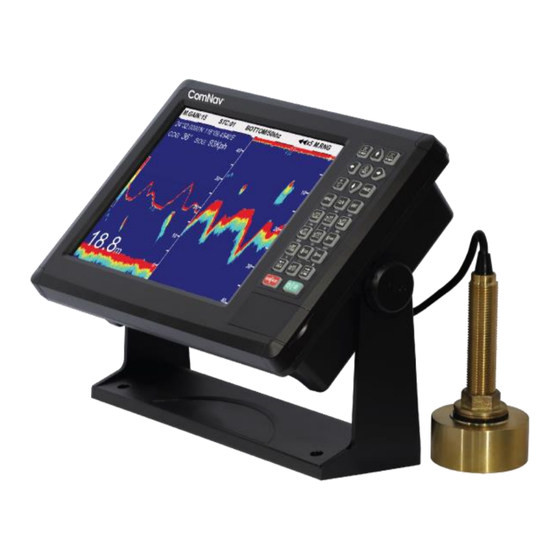
Overview The M10 Fish Finder offers a built-in GPS Chartplotter on a 10.4’’ colour screen and provides a high- resolution Echo sounder. The M10 offers real-time weather updates, memory storage capacity to store waypoints, and various connectivity options and automatic software updates to stay up to date with the latest features. -
Page 12: Installation
Installation Operation Document PN 29010119 V1.0 - 12 -... -
Page 13: Tools Required
Ensure adequate wire sizes are used to handle the expected maximum currents. Environmental Considerations • Ensure that the M10’s Operating & Storage Temperature Ranges are not exceeded. Document PN 29010119 V1.0 - 13 -... -
Page 14: Warnings And Cautions
Before operating a M10, determine if authorization or a license to operate the unit is required in your country. It is the responsibility of the end-user to obtain an operator's permit or license for the M10 for the location or country of use. -
Page 15: Getting Started With M10
This manual describes the Installation and operation of the M10 Fish Finder. Front Panel and Keyboard Functionality The Figure 2 shows a schematic of the M10 front panel showing the display, keyboard, USB and SD card locations as well as the mounting bracket. - Page 16 Key Name Description 〖Zoom in/Range↑〗 1】Map: Displays detailed information of map 2】Fish Finder: Zoom In to reduce search range ↓〗 〖 1】Map: Displays global information of map Zoom out /Range 2】Fish Finder: Zoom out to increase search range 〖 〗 1】Map: Select, move cursor Arrow Keys ←↑→↓...
- Page 17 Key Name Description ↑〗 〖 1】Map: Rotate map by 90° Rotate/Gain 2】Fish Finder: Increase gain value ↓〗 〖 1】Map: Quick menu for adding Waypoint (WPT) WPT/Gain 2】Fish Finder: Decrease gain value. 1】Map: Measure distance between two points ↑〗 〖 DIST/STC 2】Fish Finder: Increase STC value.
-
Page 18: Table 1 - Keyboard Button Description
Key Name Description Note: Sub-range is available in zoom in map, zoom in seabed and B.D. 〖 〗 1】 Map: To call navigation data. It can call the GOTO/Depth Forward Navi and Reverse Navi of waypoint, route, etc. 2】Fish Finder: Adjust draft setting value by arrow keys↑↓... -
Page 19: Operation And Settings
Operation and Settings System Overview In this section the main page and the chart displays are explained. Main Page Display The Figure 4 shows the main page display. A detailed description of the information shown in the figure is provided below. Chart direction. -
Page 20: Figure 5 - Track Info. Window
Strength and Number of GPS Satellites Visible Strength of signal Number of satellites Each bar in the above figure represents one satellite; the strength of the signal received from the satellite signal – being full of pink indicates strong signal and blank (black) means weak signal. Note: The above windows can be selected by pressing the MENU Button on the keypad twice, then in the Param. -
Page 21: Chart Display
Chart Display The Figures 6, 7, 8 and 9 show the chart, AIS, compass, and data displays. Direction Isobath level Beacon 10m-isobath 20m-isobath Danger Land Figure 6 - Chart display. Figure 7 - AIS display. Figure 8 - Compass display. Document PN 29010119 V1.0 - 21 -... -
Page 22: Chart Operation
Figure 9 - Data display. Chart Operation Move chart Press any of the ARROW buttons to move the cursor. Moving the cursor to the edge causes the chart to refresh automatically. Zoom In/Out Press the ZOOM IN/ ZOOM OUT button to Zoom in/Zoom out on the chart. Backlight Brightness Press the button with the Brightness/power symbol (Number 23 in Table 1) to adjust the brightness. -
Page 23: Main Menu Operation
Main Menu Operation Function: The main menu provides the function of calling and entering waypoint data. To reach the Main Menu, press the MENU button. Track Operation From the Main Menu, select Track List. The list provides ID, name, mileage, style and whether the track is shown in the chart. -
Page 24: Modify Waypoint
Option 2: Enter the Waypoint List to add After entering the Waypoint List, press the OK button to pop up the Waypoint operation, select Add a waypoint, and edit in the Edit waypoint. Select Save and press the OK button to add the waypoint. -
Page 25: Call Waypoint
From the Waypoint List menu select the desired waypoint, press the OK button, and select【Delete all】in the Waypoint operation menu. The system will pop up confirmation box. Select ’Yes’ to delete all waypoints. Note: The following waypoints cannot be deleted: •... -
Page 26: Add Marker
Add marker The system can store up to 10,000 markers. You can add markers using the following options. Option 1: Press the MARK button to add Press the MARK button to view the Edit marker menu and then add the marker at the cursor location. -
Page 27: Beacon Operation
From the Marker List menu, select the desired marker and press the OK button, and then select Delete marker. A pop-up confirmation box will appear, select ’Yes’ to delete it. Tips: You can select the desired marker from the chart by pressing the OK button and then select Delete markers from the pop-up menu. -
Page 28: Delete Beacon
From the Beacon List, press the arrows〖↓〗〖↑〗to select the desired beacon, then press the OK button to view Beacon operation menu, and select Set beacon. Option 3: Quick modification Press the DST button or from the Beacon List menu to modify the beacon. Note: The beacon ID cannot be modified. -
Page 29: Delete Route
Tip 1: Deleting one waypoint along the route ▪ Move the cursor to the Route Seq. If the cursor is at left bar, press to toggle it to the right. ▪ Move the cursor to the desired waypoint and press the OK button. The selected waypoint colour turn green. -
Page 30: Tide
Tide Function: The tide menu provides tide data of 202 areas in China in recent 60 years. Method: Main Menu → Accessory → Tide Operation: Press the arrows〖↓〗〖↑〗〖←〗〖→〗to toggle areas and tide station. Press〖4〗to view tide data of last day, and〖6〗for next day. Press〖2〗to view the tide data of the first day of last month and〖8〗for the first day of next month instantly. -
Page 31: Drawline
Draw line The system can record up to 200 draw-lines. Each draw-line consists of 40 points. In the settings you can choose between 8 different colours. Add Draw line on the chart Press the ARROW button to move the cursor to the desired location, then press the OK button and an Add... -
Page 32: Drawline List
Figure 11 - Draw line point operation. Draw line list Press the MENU button to view the Main Menu and select Draw line list. Select any draw line after entering the list and press the OK button to view the Draw line operation where one can find, modify, delete, and view draw line in the operation menu as shown in Figure Figure 12 - Draw line list. -
Page 33: Waypoint Navigation
Waypoint Navigation When the system is in waypoint navigation mode, an arrival alarm scope appears. The scope’s radius is the value set in Alarm settings. When the own ship sails into the alarm scope and the alarm switch is on, the system will send out a voice and text alarm. Route Navigation When the ship arrives at the first waypoint, the system will call the next waypoint along the route. -
Page 34: Alarm Settings
Figure 13 - System settings menu. Alarm Settings The alarm settings are used to set the alarm switches and alarm scopes. To edit the alarm settings, go to Param. settings and then select alarm settings and press the OK button. Press〖↓〗〖↑〗to select desired parameters, press〖←〗〖→〗to select parameter values. -
Page 35: Display And Sound Settings
Display and Sound Settings The display and sound settings are used to set nine parameters as shown in Figure 14, such as the system scene, screen backlight and volume etc. To edit, go to Param. settings and then select Display and sound and press the OK button. Press〖↓〗〖↑〗to select desired parameters, press〖←〗〖→〗to select parameter values. -
Page 36: Operation Guide
Operation guide To View the operation guide, go to Param. settings and then select Operate guide. To view the guide, press〖↓〗〖↑〗. Press the QUIT button to exit current page. Data Exchange The data exchange imports data from memory into the device / to backup data from the device to memory. -
Page 37: Ais Vessels Display Settings
The AIS vessel information will show the list of ships and their pertaining information as shown in Figure 16. Figure 16 - Ship list information. All recognizable ships will be shown in the data window. Press the arrows〖↓〗〖↑〗to view the desired ship information, such as, MMSI, name, call sign, coordinates, course, speed, location to own ship, and distance to own ship etc. -
Page 38: Enhanced A-Mode
Enhanced A-mode From the AIS functions, select Enhanced-A mode and press the OK button to switch it on/off. (Refer to Figure 16) Safety message From the AIS functions, select Safety message and press the OK button to view the Safety message. -
Page 39: Address
Address From the AIS functions, select Address and press the OK button to view the Address window as shown in Figure 19. Figure 19 – Address window. AIS static parameters From the AIS functions, select AIS static parameters and press the OK button to view the AIS static parameters window as shown in Figure 20. -
Page 40: Ais Navi Parameters
AIS Navi parameters From the AIS functions, select AIS nav parameters press the OK button to view the AIS nav parameters window as shown in Figure 21. Figure 21 - AIS nav parameters window. Document PN 29010119 V1.0 - 40 -... -
Page 41: Function Introduction
Function Introduction Image split The screen can be divided either horizontally or vertically as shown in Figure 22. This can be performed from either the map screen or the fish finder screen. On map screen: Press the MENU button to view the Main Menu, select Fish Finder. Select 01 Image Split from the Fish Finder Menu and press the arrows〖←〗〖→〗to select the image partition mode. -
Page 42: Image Partition Ratio
On map screen: Press the MENU button to view the Main Menu and select Fish Finder. Select 02 Image Speed and press the arrows 〖←〗〖→〗to adjust the image speed as shown below. On fish finder screen: Press the MENU button to view the Fish Finder Menu. Select 02 Image Speed and press the arrows 〖←〗〖→〗to adjust the image speed as shown below. -
Page 43: Scene
Figure 23 - Partition between map and fish finder shown from left to right as 3:1, 2:1, 1:1, 1:2,1:3. Scene This setting can be adjusted from either the map or the fish finder screen. On map screen: Press the MENU button to view the Main Menu, select Fish Finder. Select 04 Scene and press the arrows 〖←〗〖→〗to select image mode. -
Page 44: Figure 24 - Zoom Feature For A Horizontal And Vertical Split Images
Press the Center/Frequency button to switch between 50 kHz and 200 kHz. 4】 Frequency/Bottom Press the Center/Frequency button to switch between 50 kHz and 200 kHz. In the horizontal split, the lower/bottom image will be zoomed in, while in the vertical split the left-handed image will be zoomed in as shown in Figure. -
Page 45: Echo Colour Tone
Figure 25 - Bottom locked images for horizontal and vertical split images. Echo colour tone Three different pallet colours can be selected: Monochrome, 8 colour, and 16 colour. On map screen: Press the MENU button to view the Main Menu, select Fish Finder, and select 05 Echo Color Tone. -
Page 46: Decolouration
Figure 26 – Monochrome (Left), 8- colour (center), 16-colour (right). Decolouration The purpose of decolouration is to make the fish appear sharper. Four different settings are available. On map screen: Press the MENU button to view the Main Menu, select Fish Finder, and select 17 Decolouration, press〖←〗〖→〗to set decolouration mode. -
Page 47: Depth Alarm
2】hide VRM will be hidden. Press navigation/depth to show it. 3】Auto Shows VRM for 5 seconds after pressing the navigation/depth button and then hides for another 5 seconds. Depth Alarm The depth alarm can be set to off, depth-water, or low-water. Depth alarm setting: Press the Navigation/Depth button, VRM will appear in green color, press the arrows〖↑〗〖↓〗to adjust the position of VRM, then press the OK button. -
Page 48: Fish Alarm
Fish Alarm When the fish alarm is on and the sensor detects the right size and color, the system will display “Alert Fish Alarm with voice prompt as shown in Figure 27. Figure 27 - Fish alarm. 1】Fish Alarm On On map screen:... -
Page 49: Gain
1000 4*16 1500 4*16 2000 4*16 3000 5000 10000 Table 2 - Fish size setting for different ranges. On map screen: Press the MENU button to view the Main Menu, select Fish Finder, and select 11 Fish Alarm Level, press〖←〗〖→〗to set the fish level alarm. On fish finder screen:... -
Page 50: Range
Range Range can be set as auto or manual. 1】Setting range mode On map screen: Press the MENU button to view the Main Menu, select Fish Finder, and select 14 Range, press 〖←〗〖→〗to set range mode. On fish finder screen: Press the MENU button to view the Fish Finder Menu and select 14 Range, press 〖←〗、... -
Page 51: Interference Reduction
• Press the ROUTE /M. SFT ↓ button to adjust the range start value 3】Automatic shift Automatic shift status will be shown on the title of fish finder image. • When tracing at deep seabed, if the image of eco reaches the bottom of the screen, system will automatically switch down to the selected starting range. -
Page 52: Background Colour
Background Colour Three background colours can be selected, namely, Blue, Black and White On map screen: Press the MENU button to view the Main Menu, select Fish Finder, and select 06 Background Color, press 〖←〗、〖→〗to select background color. On fish finder screen: Press the MENU button to view the Fish Finder Menu and select 06 Background Color, press〖←〗、〖→〗to select background color. -
Page 53: Noise Reduction
Noise reduction Noise reduction is primarily used to reduce the noise caused by the phytoplankton and garbage echo reflections. Users can set the noise reduction level to low, medium or high. On map screen: Press the MENU button to view the Main Menu, select Fish Finder, and select 19 Noise Reduction, press 〖←〗、〖→〗to set noise reduction mode. -
Page 54: Sonic Speed Set
Sonic speed Set Sonic speed value is set by default to 1500 m/s. This setting can be used for most depth measurements. Adjusting the sonic speed value will affect the depth reading. If you are unfamiliar with how to set the sonic speed correction for fish detection, please do not change the initial setting of 1500 m/s. -
Page 55: Fish Finder Simulation
Figure 29 - An illustration of depth. Note the difference between sea surface and sensor. Fish Finder Simulation The Fish finder simulation function is used to show the echo pattern, as well as showing the effect of adjusting parameters such as gain, STC. Note that during simulation, frequency switch is not possible. - Page 56 Appendices Document PN 29010119 V1.0 - 56 -...
-
Page 57: Mechanical Specifications
Appendix 1 Mechanical Specifications The Figure 31 shows the dimensions of the M10 fish finder in millimeters (mm). Figure 31 - Frontal and side-view dimensions in millimeters. The Figure 32 shows how to install the M10 fish finder to the bracket. -
Page 58: Figure 33 - Counter Mounting Diagram. Units In Millimeters
The Figures 33 and 34 show the mounting diagrams for counter installations and ceiling installations respectively. Figure 33 - Counter mounting diagram. Units in millimeters. Figure 34 - Ceiling mounting diagram. Units in millimeters Document PN 29010119 V1.0 - 58 -... -
Page 59: Ports And Interfaces
Appendix 2 Ports and Interfaces The Figure 35 shows the back of the M10 showing four external interfaces labelled 1 to 4. Figure 35 – Back of the M10 showing ports. The ports 1 to 4 should be connected are shown below:... -
Page 60: Figure 36 - Nmea Interface Wiring Diagram
The figure 35 shows the NMEA interface Figure 36 - NMEA interface wiring diagram. Note: • Pins 1 and 2 are the output of GPS signal • Pins 3, 4, 5, 6 are the output of AIS signal • Pins 7 and 8 are the input of HDT Document PN 29010119 V1.0 - 60 -... -
Page 61: Ordering Information
Appendix 3 Ordering Information M10 Fish finder Part # 20130018 ComNav M10-FC Fish finder 10.4” Chartplotter Combo without Transducer 20130019 ComNav M10-FC Fish finder 10.4” Chartplotter Combo with Transducer 30130022 Radar Sonic 600W Transducer 30130023 ComNav 600W Transducer 29010119 Installation & Operation Manual Table 3 - Order Information. - Page 62 P2 Installation & Operation Document PN 29010119 V1.0 - 62 -...
-
Page 63: Warranty
ComNav does not warrant or guarantee that the Equipment will perform in accordance with the requirements of such usage. 2. ComNav reserves the right to modify the Equipment without any obligation to notify, supply or install any improvements or alterations to existing Equipment. - Page 64 The Limited Warranty will not apply with respect to any defective Equipment unless written notice of such defect is given to ComNav, by mail to the address for ComNav set forth below, or by facsimile to ComNav at 604-207-8008, and unless that written notice is received by ComNav within ten (10) days of the date upon which the defect first became known to the Purchaser.
- Page 65 Purchaser. 3. No refund of the purchase price for the Equipment will be made to the Purchaser unless ComNav is unable to remedy the defect after having a reasonable number of opportunities to do so.
-
Page 66: User Notes
User Notes User Notes Document PN 29010119 V1.0 - 66 -... - Page 67 User Notes Notes Document PN 29010119 V1.0 - 67 -...
Need help?
Do you have a question about the M10 and is the answer not in the manual?
Questions and answers