Table of Contents
Advertisement
Quick Links
Advertisement
Table of Contents

Related Manuals for Photon Systems Instruments FluorCam FC1300-C/2020

Summary of Contents for Photon Systems Instruments FluorCam FC1300-C/2020
- Page 2 Manual Version: 2024/12 © PSI (Photon Systems Instruments), spol. s r.o. www.psi.cz This document and its parts can be copied or provided to a third party only with the express permission of PSI. The contents of this manual have been verified to correspond to the specifications of the device. However, deviations cannot be ruled out.
-
Page 3: Table Of Contents
ABLE OF ONTENT Warnings and Safety Precautions ......................5 Introduction ............................6 Chlorophyll fluorescence ..........................6 Chlorophyll fluorescence measurement ....................... 7 Fluorescent Proteins ..................Error! Bookmark not defined. Suitable Samples .................... Error! Bookmark not defined. Technical Specification .......................... 8 General Information ..........................9 Device Description ............................ - Page 4 6.1.4 Light Curve Protocol............................ 25 6.1.5 Multicolor Fluorescence Wizard ......................... 26 6.1.6 Fluorescence Proteins Detection Protocols ....................26 How to Start ..............................27 6.2.1 Protocol Selection and Initial Set-up......................27 6.2.2 FC Imaging System Corrections and Calibrations ..................28 FluorCam Keywords..........................32 Warranty Terms and Conditions ......................
-
Page 5: Warnings And Safety Precautions
ARNINGS AND AFETY RECAUTIONS Read this manual carefully before operating the device. If you are not sure about something in the manual, contact the manufacturer for clarification. By accepting the device, the customer agrees to follow the instructions in this guide. Always follow corresponding manuals while working with the FluorCam device or doing the maintenance. -
Page 6: Introduction
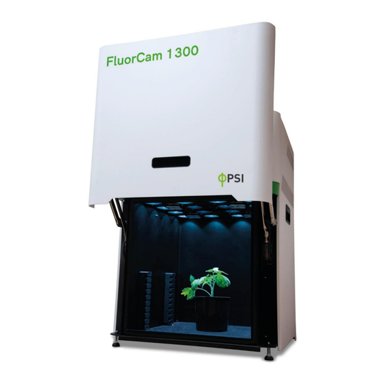
NTRODUCTION Closed FluorCam FC1300 is a highly innovative, compact system for imaging of chlorophyll fluorescence kinetics. The system provides a wealth of information about plant’s photosynthetic capacity, physiological and metabolic condition, as well as its susceptibility to various stress conditions. Fig. -
Page 7: Chlorophyll Fluorescence Measurement
The Fluorescence Imaging station uses an enhancement of the FluorCam FC-800MF Pulse Amplitude modulated (PAM) system manufactured by the Photon Systems Instruments. PSI imaging system monitors fluorescence kinetics, which provides a wealth of information about a plant’s PSII photosynthetic efficiency, physiological and metabolic condition, as well as susceptibility of photosynthetic apparatus to various stress conditions. -
Page 8: Technical Specification
ECHNICAL PECIFICATION CCD Detector Camera High resolution CCD camera TOMI-2 Resolution 1 360 × 1 024 pixels A/D Converter Resolution 16 bit (65 536 grey levels) Pixel Size 6.45 µm × 6.45 µm Frame Rate 20 frames per second for full resolution CCD Detector Wavelength 400 –... -
Page 9: General Information
Fig. 2 Closed FC1300. (A) Stand-alone version FC1300-L/2020, (B) Benchtop version FC1300-C/2020. FluorCam FC1300-C/2020 and FC1300-L/2020 feature the unique flat LED panel design which results in a highly uniform illumination across the whole imaging area (200 x 200 mm) with minimum shading effects. -
Page 10: Device Installation
The standard version contains multiple LED sources for use in excitation of chlorophyll in various ChlF protocols. The red-orange LEDs are used for measuring flashes and actinic light. The cool white LEDs are used for saturating pulse and as additional actinic light. The FAR-red LEDs are employed in estimation of F ’. -
Page 11: The Display
Unpacking: • Carefully unpack the parcel. • Place all components on a flat and firm surface. Keep them away from wet floors and counters. • Check the contents of the package and compare it with the enclosed package list. • Make sure that both, the FluorCam and the power supply, are turned off during the assemblage. -
Page 12: The Shelving System And The Cover
Fig. 5 The touch screen displays information about: (A) Available lights, (B) switched-on lights (Act1 here), (C) light calibration of the selected light, (D) selected emission filter and its spectrum, (E) device, and (F) brightness of the display. 4.4 T HELVING YSTEM AND THE OVER... - Page 13 Fig. 7 The shelving system in FC1300-L/2020. The enhanced version of FC1300-C/2020 and FC1300-L/2020 supplemented by a state-of-the-art Multi-Excitation Module can be used for detection of fluorescent proteins and dyes (such as CFP, GFP, YFP, RFP, mCherry, SYBR Green…) in seedlings in Petri dishes after the black cover is placed over the sources of actinic lights (Fig.
-
Page 14: Focusing
Fig. 8 The application of the black cover (in enhanced version only). (A) the black cover, and (B) its proper placement over the light panel. 4.5 F OCUSING The object of interest should be manually centered. The fine focus can be adjusted by the rotation of the lens using the metal handles (Fig. -
Page 15: Fluorcam 10 Software
10 S LUOR OFTWARE The FluorCam 1300 is compatible with the FluorCam10 software. Unlike FluorCam7, FluorCam10 is a 64-bit application. This change enables FluorCam10 to access more memory than 32-bit applications and so run complex protocols more smoothly. The setting of FluorCam10 resembles FluorCam7 and is quite intuitive. - Page 16 Fig. 11 Activation of FluorCam10. To activate the purchased Advanced multiple function/Automation license, the file with FC10 Automation License key has to be inserted into the software in the following way: Setup > General > Advanced > Select file > Close as described in the Fig. 12. Then, the multiple protocols can be triggered by a click on “►...
-
Page 17: The Live Tab
5.3 T Then, the “Live” tab can be used for focusing the sample of interest (this is done manually) and selection of a suitable filter and right parameters, such as light intensities, shutter, sensitivity and zoom, for the experiment. The predefined basic and advanced protocols are offered after a click on the “Wizard”... -
Page 18: The Protocol Tab
Advanced protocols, such as GFP and Multicolor, should be used in the “Snapshot mode”. The “Live” tab can be switched from the “Video mode” into the “Snapshot mode” in the following way: Setup > Device > Mode SNAP > Set Device As > Close (Fig. 14). After setting parameters, the “Get Frame”... -
Page 19: The Pre-Processing Tab
5.5 T PROCESSING The desired mask can be selected in the “Pre-processing” tab (Fig. 16). The automatic mask is applied after choosing the “Background Exclusion” button. Small objects will be excluded from the analysis when the minimal object size is given. The mask can be defined manually as well. -
Page 20: The Result Tab
5.6 T ESULT The results (curves, parameters and images) can be visualized in the “Result” tab and saved or exported in Experiment menu (Fig. 17). Fig. 17 The “Result” tab of FluorCam10. Page | 20... -
Page 21: Operation
PERATION 6.1 P DEFINED PROTOCOLS Various basic and advanced protocols (Tab. 2 and Tab. 3) can be used for the chlorophyll fluorescence analysis. Based on the type of protocol different parameters can be measured and calculated (Tab. 3). In the dark- adapted state a “measuring light- flashes” are used to measure minimum value of chlorophyll fluorescence, termed F Measuring light is of intensity too low to induce electron transport through PSII but high enough to result in minimal level of fluorescence emitted. -
Page 22: Fv/Fm Protocol
List of protocols Protocol name Description Mode Protocol for measuring multicolor Multicolor fluorescence (blue, green, red and far- SNAP red) caused by UV light Green fluorescence protein detection SNAP protocol Yellow fluorescence protein detection SNAP protocol Tab. 3 List of advanced protocols. Please note for the measurement of the dark-adapted F and F values, or the fluorescent signal of proteins, the... -
Page 23: Kautsky Curve Protocol
6.1.2 K AUTSKY URVE ROTOCOL Fig. 19 Schematics of Kautsky curve protocol. Requires dark-adaptation of plant samples. Protocol duration of 60 seconds. Kautsky protocol Measured Minimum fluorescence in dark-adapted state Measured Peak fluorescence during the initial phase of the Kautsky effect _Lss Measured Steady-state fluorescence in light... - Page 24 Quenching protocol Measured Minimum fluorescence in dark-adapted state _gauss _median Measured Maximum fluorescence in dark-adapted state – F Variable fluorescence in dark-adapted state Measured Peak fluorescence during the initial phase of the Kautsky effect – median Measured – gauss Measured –...
-
Page 25: Light Curve Protocol
6.1.4 L IGHT URVE ROTOCOL Fig. 21 Schematic of rapid light curve protocol (Light curve Act1 or Act2). Requires dark-adaptation of plant samples. Protocol duration of approx. 360 seconds. Light curve protocol Measured Minimum fluorescence in dark-adapted state Measured Maximum fluorescence in dark-adapted state Variable fluorescence in dark-adapted state _Lss Measured... -
Page 26: Multicolor Fluorescence Wizard
6.1.5 M ULTICOLOR LUORESCENCE IZARD Fig. 22 Schematics of Multicolor fluorescence wizard (Multicolor). Multicolor protocol F440 Measured Blue autofluorescence value F520 Measured Green autofluorescence value F690 Measured Chlorophyll fluorescence in red region F740 Measured Chlorophyll fluorescence in IR region Tab. 8 List of parameters for multispectral fluorescence measurement. 6.1.6 F LUORESCENCE ROTEINS... -
Page 27: How To Start
6.2 H OW TO TART There are few simple steps the user should follow before starting fluorescence measurement with FluorCam. The steps are briefly described in the following section (a detailed description of the individual steps is in the next sections). 1. -
Page 28: Fc Imaging System Corrections And Calibrations
After choosing the Actinic light intensity, test the image quality: turn on the measuring pulses and the desired actinic light and check if the signal is not too low or saturating. If the fluorescence signal is too low, increase the Sensitivity to use a best adynamic scale. TOMI-2 CCD camera A/D converter is 16-bit, therefore the signal can be acquired on the scale 0 –... - Page 29 Please note, that the correction can be done just for one light at time; therefore, select the light that will be used in the next measurement. If another light will be used in the next experiment, the calibration must be done again (from step 1) for this particular light.
- Page 30 2. In top panel menu in FluorCam10 application, select Setup (Fig. 26B) and then Size Calibration. Once the message INSERT CALIBRATION PLATE appears, the excitation light is turned on and software starts to adjust optimal exposure settings automatically. 3. Place fluorescent area of the calibration standard to the center of the field of view, wait until the image is stable and confirm it by button OK.
- Page 31 Please note: The system must be re-calibrated whenever the distance between experimental object and camera is changed (e.g.: selecting different shelf position in Closed FC version). Once the system is calibrated, this information is saved together with measured experiment. Thus, the Size calibration must be done in advance, before the experiment is measured.
-
Page 32: Fluorcam Keywords
LUOR EYWORDS Flashes – for accurate measurement of minimal fluorescence (F0) determination. The duration of flashes is controlled by shutter time. Try to keep shutter as low as possible (low resolution CCD between 0-1, high resolution CCD between 1 – 2), otherwise measuring pulses would be too strong causing actinic effect. -
Page 33: Warranty Terms And Conditions
ARRANTY ERMS AND ONDITIONS 1. This Limited Warranty applies only to the FC1300-C/2020 and FC1300-L/2020 device. It is valid for one year from the date of shipment. 2. If at any time within this warranty period the instrument does not function as warranted, return it and the manufacturer will repair or replace it at no charge.
Need help?
Do you have a question about the FluorCam FC1300-C/2020 and is the answer not in the manual?
Questions and answers