Advertisement
OVERVIEW
Hydro-X Control System is the most intelligent and versatile environmental control system on the market. lt could control up to 512 lights, 4 temperature devices, 2humidity devices, 2 CO2 devices, 9 preprogram devices. With the incredible flexibility, anyone could easily customize their own grow room system for maximum yield.
The system comes with a 3-in-1 sensor detecting temperature, humidity & light. A CO2 sensor is available for measuring CO2 level. When the measured value exceeds your custom setting range, a warning message will be sent to your smart phone. Smoke detectors are also available for smoke detection to alert you if there is a fire. Hydro-X helps you to monitor your grow environments perfectly.
Hydro-X is specially designed to set up a daily lighting management for your lighting system. Having 2 separate lines allows the user to create multiple lighting layouts (and dimming sequence) based on their individual preferences, This system can efficiently control your lighting system by running a schedule with advanced functions like auto dimming, overheat shutdown, sunrise &sunset simulation.
Hydro-X can control almost all kinds of devices in your grow rooms with its 4 types of device stations. Temperature device stations, humidity device stations, CO2 device stations and program device stations are designed to be connected to different devices for centralized control, Hydro-X offers a more smart and flexible approach for the connection of the devices you want to control.
Hydro-X keeps pace with the times, it has the ability to connect to the network directly with a standard network cable. After downloading the app, you can monitor and control the environment of your grow rooms anytime and anywhere, You could read the historical data through graph on your smartphone and receive warning messages if the growing environment exceeds your setpoints. A micro-SD card is also available for data logging if the Internet is unavailable. With Hydro-X, you can monitor and control the growing environment at your fingertips.
FACTS
Here are some important things to consider when using the Hydro-X Control System.
- Each set of Hydro-X Control System can connect to one 3-in-1 sensor, one C02 sensor and one PAR sensor, up to five optional water detectors and five optional smoke detectors. The 3-in-1 sensor is used to detect temperature, humidity and light, the CO2 sensor is used to detect CO2 level, PAR sensor can detect photosynthetically active radiation from light source. and the water and smoke detectors are used to detect water leak and prevent fire respectively.
- Each lighting line MUST have a single wattage/type of fixture connected to it. You cannot mix fixtures with different wattages on the same line interconnect wiring. When connected to lights which are controlled by digital signal (such as ThinkGrow DE ballast), 256 lights can be controlled on each line, with potentially 512 lights controlled in total. A lighting control adapter (signal converter) is available for controlling the traditional lights which are controlled by analog signal (0-10v), such as Gavita etc. Due to the limitation of the analog signal, the system can control up to 40 traditional ballasts on each line, 80 traditional ballasts in total on both lines.
- Various devices (such as for Temp/ Humid /CO2, etc.) can be connected to this unit through 4 types of different Device Stations, Each device has its own and dedicated device station, which can be purchased separately depending on your needs. Don' t mix up device station for different device.
- Sensors, Device Stations and Ballasts are connected to main controller by using RJ12 cables to daisy-chain all the devices together. Each of the sensors and devices stations comes with an RJ12 "T" splitter and RJ12 cables. Various length pre-crimped RJ12 cables and additional T-shape splitters can be purchased separately.
- A maximum distance of 1000 f/ 300 meters between the HCS-1 Hydro-X Control System and the devices to be controlled is needed.
- Follow all local and national electrical codes for installation requirements.
- The Hydro-X is designed for indoor use only. lt is recommended to use our Trolmaster's accessories for good performance.
COMPONENTS

- Controller
- Back Plate (Bracket)
- 4 ft RJ12 Cable
- T-Shape Splitter
- 12VDC Power Supply
- 3-in-1 Sensor
- 16 ft RJ12 Cable
INSTALLATION
Determine where to locate the main controller. The controller comes with a simple to use DlN type bracket. Pull the 4 tabs outward to release the bracket from the unit, mount the bracket to a wall or surface, place the unit back on the bracket and press the 4 tabs back in to lock the unit in place. The interconnecting RJ12 communication cables are available in different lengths, select the correct length for your application. The HCS-1 Hydro-X Control System is supplied with a 4ft and 16ft cable. These interconnecting RJ12 cables are also available in lengths of 25ft and 50ft. Select the correct length for your application.

CONNECTIONS

- Power Connection:
Connect the plug-in power supply to the power (DC) connector. - Sensor connection:
Connect the RJ12 cable to the SENSORS connector and connect to a splitter on the other end. Plug the 3-in-1 sensor to the splitter for connection. The other connector on the splitter can be used to continuously connect to the next splitter. Connect a CO2 sensor to the 2nd splitter. Repeat the procedure and connect one or more smoke detector(s) if needed. Press the small button on the smoke detector, the Hydro-X will automatically assign an address to the unit sequentially. - Device Station Connection (main controller needs to be powered on)
Connect the cable going from the DEVlCES connector to the first Device Station to be connected. Use the T-shape splitter and short RJ cable so that the first cable can continue on to be connected to the next T-shape splitter (Device Station) to be connected. Plug the Device Station to the wall outlet for power supply. Press the small button on the device station, the system will automatically assign an address to the device station in sequence. Repeat this process until all device stations are connected to the main controller. - Light Connection
- For HlD Lights:
Connect the cable going from LlNE 1 to the first digital ballast to be connected. Use the T-shape splitter and short RJ cable so that the first cable can continue on to be connected to the next T-shape splitter (ballast) to be connected. Repeat this process until all ballasts (fixtures) are connected to the LINE 1. Connect more lights through the LlNE 2 port. Repeat the same procedure on LINE 2.

- Controller
- Splitter
- HID Lights
- For Traditional Lights:
If connected to traditional lights which are controlled by analog signal (0-10v) such as Gavita fixtures, a lighting control adapter (signal converter) is necessary to convert the digital signal into analog signal. The connection is similar as above but with a signal converter connected between ballast and controller. First, connect the signal converter to the LlNE 1 or LlNE 2 connector and then connect to a splitter on the other end, Finally, use another RJ12 cable to connect between the splitter and the analog ballast. See the connection diagram.

- Controller
- Lighting Control Adapter
- Splitter
- Traditional Lights
- For HlD Lights:


Each line can be set up to be a "staged" dimming zone. In other words, each zone has its own independent dimming temperature setting as well as the dimming action. Having 2 lines allows the user to create multiple lighting layouts (and dimming sequences) based on their individual preferences. Some examples are shown below.

- Internet Connection
This unit has the feature of connecting the network for remote control. User can use a standard network cable for connection through the INTERNET connector.
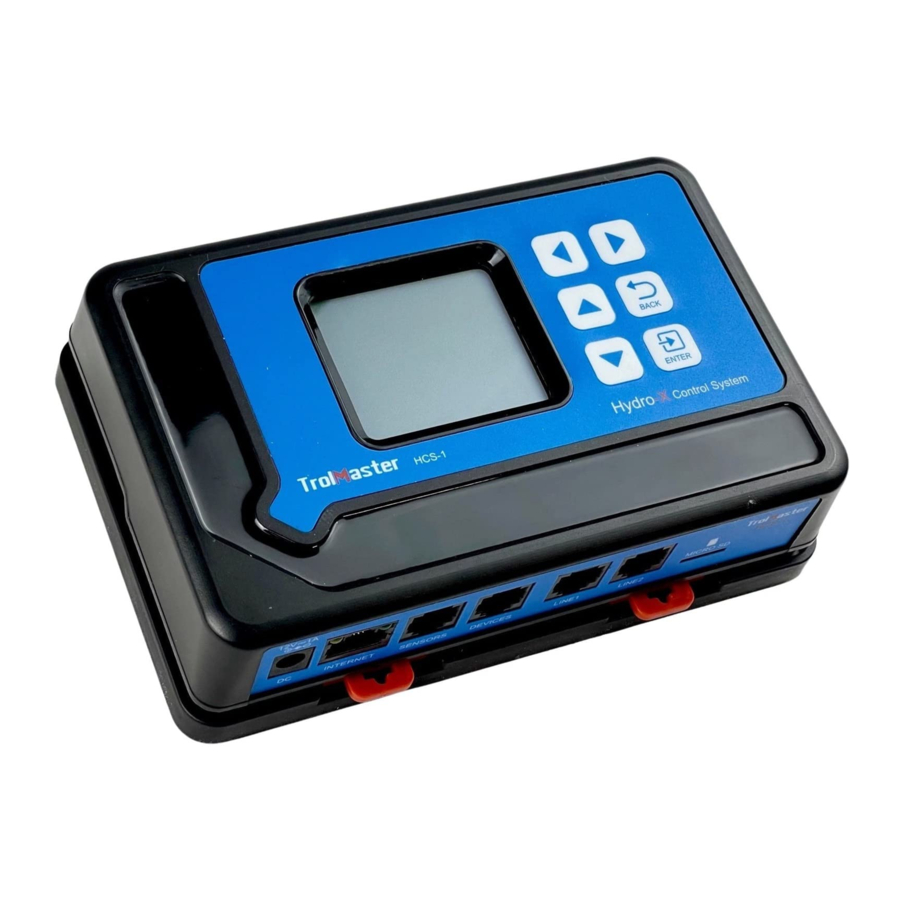
BUTTONS
The HCS-1 Hydro-X Control System is extremely easy to use. The backlit 128x128 LCD display will provide the user with the current conditions and access to all settings all settings. All settings can be accessed by using the 6 pushbuttons on the front of the unit. The button functions are described below.

UP/DOWN: The Up and Down buttons move the cursor up and down to select the item on the LCD display.
LEFT/RIGHT: The Left and Right buttons move the cursor to previous page or next page, left item or right item.
BACK: The Back button goes backwards to the previous page.
ENTER: The Enter button is used to open the menu item to be changed as well as to accept and "enter" the new setpoint into memory.
Familiarize yourself with the function of the 6 buttons on the front of the HCS-1 Hydro-X Control System in order to able to access settings, and to better understand how to use the HCS-1 Hydro-X Control System to its greatest potential.
Start Settings
Once you have connected all devices, sensors and fixtures to the HCS-1 Hydro-X Control System, we can start using the unit.
Connect the plug-in power supply to the power connector on the bottom of theHCS-1 Hydro-X Control System. HCS-1 Hydro-X Control System will turn on and boot up.
lf it is the first time you have used the HCS-1 Hydro-X Control System, when you power on the HCS-1 Hydro-X Control System the Welcome screen/page will be displayed.

*NOTE: Press ENTER button to first go to the Configuration page and begin set-up.
Time Setting: please refer to P18 for the time setting so as to change the defaulttime into the current time before use.

Main Menu

- The main menu displays three elements:
Temperature Value (°F) eg: 78.8°F
Humidity Value (%) eg: 20.2%
CO2 Level (PPM) eg: 1200 PPM
The top title bar indicates current date & time:
Month/Date eg: 09/07
Hour/Minute eg: 18:20
Day Mode![]()
Night Mode![]()
Alarm Activated![]()
Internet Connected![]()
No Network Connection (no icon)
*NOTE: Download the TrolMaster app from App Store or Google Play. - On the Main Menu page, press LEFT button
![]() to get access to Devices Status page. The screen will show devices in 3 states.
to get access to Devices Status page. The screen will show devices in 3 states.
![]()
- State One:
![]() Highlighted and with "ON" indicates the device is connected and under working condition (activated).
Highlighted and with "ON" indicates the device is connected and under working condition (activated). - State Two:
![]() Highlighted and without "ON" indicates the device is connected but not under working condition (standby).
Highlighted and without "ON" indicates the device is connected but not under working condition (standby). - State Three:
![]() Non-highlighted indicates no device station is connected to this address.
Non-highlighted indicates no device station is connected to this address.
- State One:
- On the Main Menu page, press the RlGHT button
![]() to get access to Alarm Message page. The LCD screen will show records of all alarm messages.
to get access to Alarm Message page. The LCD screen will show records of all alarm messages.
![]()
*NOTE:- On the Devices Status page, the device states are not suitable to lighting devices. The LCD screen will display the lighting status for two lighting lines L1 & L2.
- Do not remove the Micro-SD card in the main screen (showing Temperature, Humidity & CO2). Otherwise, it is easy to cause damage to the card.


 to get access to Devices Status page. The screen will show devices in 3 states.
 Highlighted and with "ON" indicates the device is connected and under working condition (activated).
 Highlighted and without "ON" indicates the device is connected but not under working condition (standby).
 Non-highlighted indicates no device station is connected to this address.
 to get access to Alarm Message page. The LCD screen will show records of all alarm messages.
Setting Page

On the Main Menu page, Device Status page or Alarm Message page, press ENTER button  to get access to the SETTING page. The LCD screen will display 6 subjects (Light/Temp/Humid/CO2/Program/System) as shown on the picture, You can move the cursor (UP/DOWN/LEFT/RIGHT) to select the subject you wish to edit setting.
Lighting Settings

- On the Setting page, select the Light subject and then press ENTER button
![]() to confirm your selection. The screen will display Line 1 and Line 2. Press UP button
to confirm your selection. The screen will display Line 1 and Line 2. Press UP button ![]() or DOWN button
or DOWN button ![]() to select Line 1 or Line 2. Then press ENTER button
to select Line 1 or Line 2. Then press ENTER button ![]() to get into the configuration page.
to get into the configuration page. - Use the UP and DOWN button to select the optional item. Press ENTER button, the digits will be flashing, then press UP or DOWN button for change setting. Finally, press ENTER button to confirm and save change.
![]()
Wattage: Select the wattage of ballast that will be connected to this line.
Qutput Max: Select the wattage that you would like to operate the fixtures in increment of 25 watt. User can select any setting between 600 watts and 1150 watts for the 1000 watt fixture.
On at: The time of day that the lights for that LINE 1 will be turned ON.
Off at: The time of day that the lights for that LlNE 1 will be turned OFF.
Dim at: Select the temperature you want the lights within each line to dim.
Stop at: The max temperature that the growing area can get to before shutting down the lights. Normally, set at least 5°F up to 10 degrees F above the "Dim at" setting.
Sun R/S time: simulate Sunrise and Sunset by slowly raising and lowering the lighting level (brightness). User can select from 0 minute (off) to 30 minutes in 5-minute increments for the Sunrise/Sunset feature. - The lighting configurations of Line 2 is same as the setting of Line 1.
![]()
 or DOWN button
  to select Line 1 or Line 2. Then press ENTER button

Temperature Settings

- On the Setting page, select the Temp subject and then press ENTER button
![]() to access the Temp setting page. Use the Up button
to access the Temp setting page. Use the Up button ![]() or Down button
or Down button ![]() to select the device or Alarm Setting.
to select the device or Alarm Setting. - When the Device 1 is selected, user can set the temperature setpoint for Day/Night mode for the Device 1. The unit will automatically turn ON the Temp Device 1 when the measured temperature is ABOVE or BELOW the setpoint. Press ENTER button and the Above or Below text will be flashing. Press UP or DOWN button to change between Above and Below. Finally, press ENTER button to confirm and save the change.
![]()
For example: Turn on device when temp reaches Above setpoint for Cooling devices; Turn on device when temp reaches the Below setpoint for Heating devices.
Use UP and DOWN button to select Day mode or Night mode, the selected item will be highlighted. Press ENTER button and the current temperature value will be flashing. Press UP or DOWN button to change the setpoint. Finally, press ENTER button to confirm and save the change. The LCD will display "Setting saved". - Press DOWN button to select and enter the Temp Alarm page. The screen will display the Min/Max setpoint. Press UP or DOWN button to select the Min or Max setpoint. The selected item will be highlighted. Then press ENTER button again, the current temperature setpoint will be flashing. Press UP or DOWN button to change the setpoint. Finally, press ENTER button to confirm and save the change. The LCD will display "Setting saved".
When the Temperature level exceeds the setting range, the unit will send a warning message to your smartphone.
The setting procedure of other Temp Device Station is same as above.
![]()


Humidty Settings

- On the Setting page, select the Humid subject and then press ENTER button
![]() to access the Humid setting page. Use the Up button
to access the Humid setting page. Use the Up button ![]() or Down button
or Down button ![]() to select the Device 1 or Device 2 or Alarm setting.
to select the Device 1 or Device 2 or Alarm setting. - When the Device 1 is selected, user can set the humidity setpoint for Day/ Night mode for the Device 1. The unit will automatically turn ON the Humid Device 1 when the measured humidity is ABOVE or BELOW the setpoint.
Press ENTER button and the Above or Below text will be flashing.
Press UP or DOWN button to change between Above and Below.
Finally, press ENTER button to confirm and save the change. The LCD screen will display "Setting saved".
![]()
For example: Turn on device when humidity level is Above setpoint for Dehumidifier; Turn on device when humidity level is Below setpoint for Humidifier. Use UP and DOWN button to select Day mode or Night mode, the selected item will be highlighted. Press ENTER button and the current Humid value will be flashing. Press UP or DOWN button to change the setpoint. Finally, press ENTER button to confirm and save the change. The LCD will display "Setting saved". - Press DOWN button to select and enter the Humid Alarm page. The screen will display the Min/Max setpoint. Press UP or DOWN button to select the Min or Max setpoint. The selected item will be highlighted. Then press ENTER button again, the current humidity setpoint will be flashing. Press UP or DOWN button to change the setpoint. Finally, press ENTER button to confirm and save the change. The LCD will display "Setting saved".
When the humidity level exceeds the setting range, the unit will send a warning message to your smartphone.
The setting procedure of Humid Device Station 2 is same as above.
![]()


CO2 Settings

- On the Setting page, select the CO2 subject and then press ENTER button
![]() to access the CO2 setting page. Use the Up button
to access the CO2 setting page. Use the Up button ![]() or Down button
or Down button ![]() to select the Device 1 or Device 2 or Alarm Setting.
to select the Device 1 or Device 2 or Alarm Setting. - When the Device 1 is selected, user can set the CO2 setpoint during Daytime for the Device 1. The unit will automatically turn ON the CO2 Device 1 when the measured CO2 level is ABOVE or BELOW the setpoint. Press ENTER button and the Above or Below text will be flashing. Press UP or DOWN button to change between Above and Below. Finally, press ENTER button to confirm and save the change. The LCD screen will display "Setting saved".
![]()
For example: Turn on device when CO2 level reaches the Above setpoint for Exhaust fan; Turn on device when CO2 level reaches the Below setpoint forCO2 Generator or Regulator.
User can set the setpoint for Day mode. Press DOWN button to select the CO2 value. Press ENTER button and the current CO2 value will be flashing. Press UP or DOWN to change the CO2 setpoint with the increment of 10. Finally, press ENTER button to confirm and save the change.
User can also turn ON or OFF the Fuzzy Logic mode. Press DOWN button to select the Fuzzy subject and then press ENTER button. The ON or OFF text will be flashing. Then press UP or DOWN button to change between ON and OFF status. Finally, press ENTER button to confirm and save the change.
*NOTE:- Fuzzy Logic mode is only for the control of CO2 Regulator. Do not turn on while connecting to a CO2 generator.
- Fuzzy Logic mode counters rising or falling CO2 levels by quickly activating the CO2 selenoid valve, allowing CO2 levels to be controlled more precisely.
- Press DOWN button to select and enter the CO2 Alarm page. The screen will display the Min / Max setpoint. Press UP or DOWN button to select the Min or Max setpoint. The selected item will be highlighted.
![]()
Then press ENTER button again, the current CO2 setpoint will be flashing. Press UP or DOWN button to change the setpoint. Finally, press ENTER button to confirm and save the change. The LCD will display "Setting saved".
When the CO2 level exceeds the setting range, the unit will send a warning message to your smartphone.
The setting procedure of CO2 Device Station 2 is same as above.


Program Settings

- On the Setting page, select the Program subject and then press ENTER button
![]() to confirm your selection. The screen will display a total of 9 preset numbers: 1, 2, 3...9. You can assign total 9 additional devices with the preset numbers from program device 1 to program device 9.
to confirm your selection. The screen will display a total of 9 preset numbers: 1, 2, 3...9. You can assign total 9 additional devices with the preset numbers from program device 1 to program device 9. - Press number 1 to enter into the Program Device 1 page. There are two timing control type: By Schedule & By Recycle. Press ENTER button, the TICK icon will be highlighted and flashing. Then press UP or DOWN button to select By Schedule or By Recycle. Finally, press ENTER button to confirm your selection and the LCD will display "setting saved". Press UP or DOWN button to select the subdirectory you desire to change.

The selected item will be highlighted, press ENTER button it will be flashing. Press UP or DOWN button to change the time and press ENTER button to save your change. The number of times (frequency) starts from 1 to 100.

By Schedule:
On: The start time of continuous working time of the Program Device 1.
Off: The finish time of continuous working time of the Program Device 1.
By Recyle:
Start: The start time of cycle working time of the Program Device 1.
ON Time: The duration of working time per cycle for the Program Device 1. OFF Time: The duration of non-working time per cycle for the Program
Device 1.
Times: the number of times of the daily working cycle.
The setting procedure of other Program Device Stations is same as above.
*NOTE: lf the total cycle time exceeds 24 hours, the maximum cycle times will be reduced automatically.
System Settings

- On the Setting page, select the System subject and then press ENTER button
![]() to confirm your selection. There are 6 subjects:
to confirm your selection. There are 6 subjects:
Temp Format: Select whether to display F or C for temperature measurements.
Time Setting: Enter the time setting page.
Override: Enter the Override page.
Serial Number: Show the device serial number.
System Reset: Enter the system reset page.
Calibration: Enter the temperature humidity and CO2 sensor calibration page.
DeadBand: Enter the temperature humidity and CO2 deadband setting page. - Time Setting:
Press UP or DOWN, LEFT or RIGHT buttons to select subject and press ENTER to start setting. Press UP or Down for change and press ENTER button for save. The 1st line is for time (Hour_Minute_Second) and the 2nd line is for date (Month_Date_Year).
![]()
- Override:
When Override function is selected on the System page, the cursor will be flashing. Use UP or DOWN, LEFT or RIGHT to move to the device you want to manually override (force) to turn on or off. Press ENTER button to active the override effect. The effective time is 10 mintues. After that, the device will back to its original status.
![]()
- CO2 Calibration:
After used for some time, the CO2 sensor may need to be recalibrated if tolerance occurred.
Press Enter and UP or DOWN button to adjust the calibration level if you have an accurate reference. Otherwise, the recommended level will be 400. Press Start button to start with the CO2 calibration process.
![]()
*NOTE: Do NOT exhale or breathe near the sensor while activatirg the calibration function. - System Reset:
Devices Reset: When using this function, the unit will delete all addresses assigned to the connected Device Stations. User can reconnect Device Stations for resign addresses.
Factory Reset: This function will restore the unit to factory default settings.
Firmware Update: Update a new firmware to fix bugs or add new functions to the unit. Visit our website to find out update version.
![]()


REGISTRATION
TrolMaster Agro Instruments Co., Ltd. will occasionally release updated firmware for the HCS-1 Hydro-X Control System.
By registering your HCS-1 Hydro-X Control System on our website www.trolmaster.com we can notify you when an update is available.
We will not sell, rent or share your personal information.
TROUBLESHOOTING
Some of the most common issues or problems can be found within this section. Before returning the unit for service, please consult the troubleshooting points below, additional information can be found online at www.trolmaster.com
| PROBLEM | RESOLUTION |
| The HCS-1 Hydro-X Control System is connected to power, but it does not seem to be working/no display | Check the low-volt power supply is plugged in properly to the HCS-1 Hydro-X Control System. |
| The temperature, humidity and CO2 value on the main screen display horizontal line or flashing. | The horizontal line indicates that the corresponding sensor is wrong, and the flashing represents the parameter beyond the alarm range. |
| The MOON icon is flashing. | Alarm during day mode and night state. (When 2 lines of lights are not in OFF status while the photocell detects the night state.) |
| The BELL icon is flashing. | Alarming state including temperature /Humidity/ CO2 value exceeds the setting range, daytime and night state alarm, smoke alarm. |
| According to the setting parameters, the lighting should not be OFF but acutall it is in OFF state. | Make sure whether it is no more than 15 minutes after the light has been turn. OFF. The lighting will maintian the OFF state during the 15-minute restrike time. |
| The acutal ON/OFF state of Device is inconsistent with the calculated parameter. | Please perform the OVERRIDE function. |
| No data about temperature and humidity, no date about CO2. | Make sure not to mix up the interface of SENSORS, DEVICES, LINE 1 & LINE 2. |
| The LED indicator keeps flashing quickly and can not be assigned to the main controller after pressing the button of device station or smoke detector. | Make sure whether the corresponding device station or the smoke detecor meets its maximum connections (2 temp device stations, 2 humid device stations, 2 CO2 device stations, 9 program device stations, 20 smoke detectors). Device station that has been added but not connected will still occupy the address assignment. |

DO NOT allow the Hydro-X Control System to be exposed to water or excessive heat, DO NOT open or attempt to repair or disassemble the controller, as there are no user-serviceable parts inside. Opening the controller will void the warranty.
lf the surface of Hydro-X is dirty, wipe it with a dry towel.
The Hydro-X operates under natural ventilation conditions.
SPECIFICATIONS
| Input Voltage | 100-240VAC,50/60Hz |
| Certifications | ETL/FCC |
| Degree of Ingress Protection | IP20 |
| Max Number of HlD Fixtures | 256*2 |
| Max Distance to Device to be connected | 1000 meters |
| 3-in-one (Temp/Humid/CO2/Light) Sensor C02 Sensor Smoke Detector (optional) | Max 1pc per set Max 1pc per set Max 5pcs pet set |
| Temp Device Stations | Max 4pcs per set |
| Humid Device Stations CO2 Device Stations | Max 2pcs per set Max 2pcs per set |
| Program Device Stations | Max 9pcs per set |
| Temperature Range | 32-138.2°F |
| Temperature Accuracy | ±0.36°F |
| Temperature Deadband | 3°F (1~15) |
| Humidity Range | 5-95% |
| Humidity Accuracy | ±5% |
| Humidity Deadband | 3°F (1-15) |
| CO2 Range | 0-2000 PPM |
| CO2 Accuracy | ±30 PPM |
| CO2 Deadband | 50ppm(10~250) |
| Working Environments | Temperature 32-122°F |
| Humidity ≤90% |
Documents / Resources
References
Download manual
Here you can download full pdf version of manual, it may contain additional safety instructions, warranty information, FCC rules, etc.
Advertisement


Need help?
Do you have a question about the Hydro-X and is the answer not in the manual?
Questions and answers