Advertisement
- 1 Introduction
- 2 Features and Specifications
-
3
Operating Instructions
- 3.1 Operation Panel
- 3.2 DC Voltage Measurement
- 3.3 AC Voltage Measurement
- 3.4 DC Current Measurement
- 3.5 AC Current Measurement
- 3.6 Resistance (Ω) Measurement
- 3.7 Capacitance (C) Measurement
- 3.8 Diode and Continuity Test
- 3.9 Frequency (f) Measurement
- 3.10 Data Hold and Backlight On/Off
- 3.11 Auto Power On/Off
- 4 Trouble shooting
- 5 Instrument Maintenance
- 6 Safety Precautions
- 7 Documents / Resources
Introduction
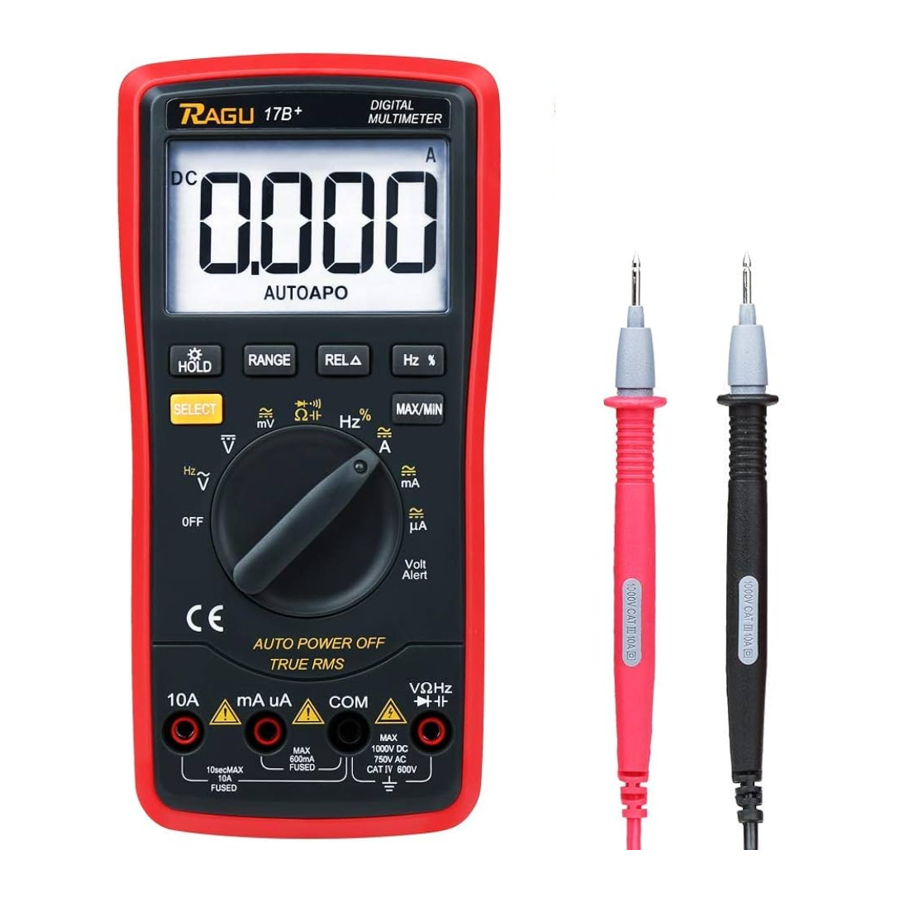
As a battery-driven 3 5/6 automatic digital instrument, RAGU 17B is a perfect combination of stable performance, high precision and high reliability. The instrument is equipped with a LCD display of text height 21mm which is designed for delivering clear and accurate readings. High voltage alarm, 15s backlight and overload protection make it convenient to use. RAGU 17B can be used to measure the DC/AC voltage, DC/AC current, resistance, capacitance, diode, continuity, true RMS and frequency. It is an ideal tool in laboratory and factory as well as for radio fans and family due to outstanding performances.
Features and Specifications
General Features
- Display: LCD
- Maximum Display: 5999 (5 5/6) counts automatic polarity display
- Measuring Method: Dual integral A/D converter
- Sampling Rate: Approx. 3 times per second
- Over Range Indication: Display "OL"
- Low Battery Indication: "
![]() " symbol appears
" symbol appears - Operation Environment: (0〜40)℃, Relative Humidity: 80%
- Power Supply: 1pc 9V (NEDA1604/6F22) battery
- Dimension (size): 184 x 90 x 46 mm (L x W x H)
- Weight: Approx. 320g (including 1pc 9V battery)
- Accessories: Instruction manual (1 pc), Test leads (1 pair), 9V Battery (1 pc, NEDA1604/6F22 or equivalent model).
 " symbol appears
Technical Features
- Accuracy: ± (a% × reading+least significant digits), at (23±5)℃, relative humidity <75%. Warranty is one year, starting on shipping date.
- The functions with "▲" are available for RAGU 17B.
Measurement Functions and Specifications Supported by 17B DC voltage (DCV) ![]()
AC voltage (ACV) ![]()
AC/DC current (mA/uA) ![]()
AC/DC current (10A) ![]()
Resistance \diode\ on-off test ![]()
Capacitance (c) ![]()
Frequency (f) ![]()
Temperature (℃/℉) Auto power on-off ![]()
Backlight display ![]()
Unit symbol display ![]()
True RMS measurement ![]()
High-voltage output LED measurement Electric field detection ![]()
- Specifications
- DC voltage (DCV)
Range Accuracy Resolution 600mV (0.5%+3) 0.1mV 6V 0.001V 60V 0.01V 600V 0.1V 1000V (0.8%+10) 1V Input impedance: 10MΩ.
Overload protection: 550V DC or AC peak at the range of 200mV; 1000V DC or 750V AC peak for rest ranges. - AC voltage RMS (ACV)
Range Accuracy Resolution 600mV (0.8%+5) 0.1mV 6V 1mV 60V 10mV 600V 100mV 750V (1.2%+10) 1V Input impedance: 10MΩ.
Frequency response: 40Hz~1kHz(standard sine wave and triangular wave); 40Hz~200Hz (other waveforms). - DC current
Range Accuracy Resolution 600uA (0.8%+10) 0.1uA 6000uA 0.001mA 60mA 0.01A 600mA 0.1A 10A (2.0%+30) 1A Maximum allowable pressure drop: 600mv.
Overload protection: 600mA: 600mA/250V fast acting glass fuse;
10A: 10A/250V fast acting ceramic fuse. - AC current
Range Accuracy Resolution 600uA (0.8%+10) 0.1uA 6000uA 0.001mA 60mA 0.01A 600mA 0.1A 10A (2.0%+30) 1A Maximum allowable pressure drop: 600mv.
Overload protection: 600mA: 600mA/250V fast acting glass fuse;
10A: 10A/250V fast acting ceramic fuse.
Frequency response: 40Hz~1kHz(standard sine wave and triangular wave); 40Hz~200Hz (other waveforms).
Display: True RMS. - Resistance (Ω)
Range Accuracy Resolution 600Ω (0.8%+5) 0.1Ω 6kΩ (0.8%+3) 1Ω 60kΩ 10Ω 600kΩ 100Ω 6MΩ 1kΩ 60MΩ (1.0%+25) 10kΩ Open-circuit voltage: less than 3V.
Overload protection: 550V DC or AC peak.
Note:- When selecting the 600Ω range, you should short-circuit test leads at first to measure the wire resistance, and then deduct it from the actual resistance.
- When measuring the resistance is greater than 1MΩ, the instrument will take several seconds to make the reading stable. It is normal.
- NCV measurement
When switch to the NCV test function, the instrument approached electric field, beep sound changes according to the strength of the electric field. Intermittent beep sounds are also from strong to weak. - Capacitance (C)
Range Accuracy Resolution 60nF (3.5%+20) 10pF 600nF 100pF 6uF 1nF 60uF 10nF 600uF (5.0%+10) 100nF 6000uF 1uF Overload protection: 550V DC or AC peak.
- Frequency (f)
Range Accuracy Resolution 10HZ (0.1%+3) 0.01Hz 100HZ 0.1Hz 1kHz 1Hz 10kHz 10Hz 100kHz 100Hz 1MHz/20MHz 1kHz/10kHz Input sensitivity: 1V RMS.
Overload protection: 550V DC or AC peak (not more than 10 seconds).
Range Display value Test Conditions ![]()
Diode has a forward voltage drop Forward DC current is about 1mA; open-circuit voltage is about 3V A long sound comes from buzzer when testing the resistance of two tested points is less than 50± 20Ω Open-circuit voltage is about 3V, press the Select button to choose either of two modes Overload protection: 550V DC or AC peak.
![]()
At this range, it is prohibited to input the voltage for safety concerns.
- DC voltage (DCV)


Operating Instructions
Operation Panel

- LCD display;
- Manual Range button
- Data Hold button(press and hold the button for 3 seconds to turn on/off the light);
- Select button;
- Relative selection button;
- Frequency and duty cycle conversion button;
- Function selection switch;
- mA/uA current input socket;
- 10A current input socket;
- COM input; negative input socket for black test lead;
- Voltage, resistance, diodes, capacitors, frequency input;
- MAX/MIN measurements button.
DC Voltage Measurement
- Insert red test lead and black test lead to V/Ω/Hz and COM input jacks respectively.
- Rotate function selection switch to
![]() , which is for DC voltage measurement.
, which is for DC voltage measurement. - Connect test end of the test lead with circuit under test. Polarity of red test lead and voltage value under test will be indicated on the display screen at the same time.
- Read the measured value from the display screen.

Note:
- Don't measure voltage over DC 1000V or AC 750V. Otherwise, it may cause damage to the meter.
- When measuring high voltage, more attention should be paid to personal safety and avoid your body getting in touch with high voltage circuit.
- After measuring, disconnect test leads from circuit under test immediately.
AC Voltage Measurement
- Insert red test lead and black test lead into V/Ω/Hz and COM input jacks respectively.
- Rotate function selection switch to
![]() , which is for AC voltage measurement.
, which is for AC voltage measurement. - Connect test end of the test lead with circuit under test.
- Read the measured value from the display screen.
Note:
- Before measuring, since the influences of previous measurements or test environment around, the values showed on display screen maybe not return 0. Don't worry about that, it will not affect the measuring results for this time.
- Do not measure input voltage which is higher than 750V RMS. Otherwise, it may cause damage to the meter.
- When measuring high voltage, please pay more attention to prevent electric shock.
- After measuring, disconnect test lead from circuit under test immediately.
DC Current Measurement
- Insert the black test lead into COM input jack and red one into mA/uA jack (Max 600mA), or insert the red one into 10A input jack (Max 10A). The initiate state of the measuring current is DC current. Press "Select" button to switch the mode.
- Rotate function selection switch to DCA. Then connect the test leads to the tested circuit in series, the tested current value and the current polarity of the point, where the red test lead is contacted, will be displayed on the screen simultaneously.
Note:
- Turn off the power of the circuit before connecting the test leads to the circuit in series.
- Select the maximum range if you don't know the extract current range, then adjust the range according to the measured results on the display screen. If "OL" is showed, it indicates the tested current value has exceeded the present range limit, please select higher range to complete the measurement.
- The maximum input value is 600mA or 10A (depending on the socket where the red test lead is contacted). For mA input, the overrated current will lead to fuse melt. For 10A input, the measuring time should not exceed 10 seconds for each time, the overrated current will lead to overheat or even damage the meter.
- Do not connect the test leads to other circuits in parallel after connecting the test leads to current input sockets, it will damage the fuse and the meter.
- After measuring, turn off the power of the circuit, then disconnect test lead from circuit under test immediately (especially for high current measurements).
- The input voltage between current input socket and COM socket, cannot be higher than 36V DC or 25V AC.
AC Current Measurement
- Insert the black test lead into COM input jack and red one into mA/uA jack (Max 600mA), or insert the red one into 10A input jack (Max 10A). The initiate state of the measuring current is DC current. Press the "Select" button to switch to AC current measurement mode.
- Rotate function selection switch to DCA. Then connect the test leads to the tested circuit in series, the tested current value and the current polarity of the point, where the red test lead is contacted, will be displayed on the screen simultaneously.
Note:
- Turn off the power of the circuit before connecting the test leads to the circuit in series.
- Select the maximum range if you don't know the extract current range, then adjust the range according to the measured results on the display screen. If "OL" showed, it indicates the tested current value has exceeded the present range limit, please select higher range to complete the measurement.
- The maximum input value is 600mA or 10A (depending on the socket where the red test lead is contacted). For mA input, the overrated current will lead to fuse melt. For 10A input, the measuring time should not exceed 10 seconds for each time, the overrated current will lead to overheat or even damage the meter.
- Do not connect the test leads to other circuits in parallel after connecting the test leads to current input sockets, it will damage the fuse and the meter.
- After measuring, turn off the power of the circuit, then disconnect test lead from circuit under test immediately (especially for high current measurements).
- The input voltage between current input socket and COM socket, cannot be higher than 36V DC or 25V AC.
Resistance (Ω) Measurement
- Insert the black test lead into COM input jack and red one into V/Ω/Hz input jack.
- Rotate the range selection switch to
![]() , press the "Select" button, choose auto resistance measurement.
, press the "Select" button, choose auto resistance measurement. - Cross connect the test leads to the tested resistor.
 , press the "Select" button, choose auto resistance measurement.
Note:
- If "OL" showed on display screen, it indicates that the tested resistor is open-circuit or the tested value has exceeded the present range limit. When measuring the resistance is higher than 1MΩ, the instrument will take several seconds to make the reading stable. It is normal when measuring the high resistance.
- When measuring the low resistance, please short-circuit the test leads at first to test the wire resistance, and then deduct it from the actual resistance to get the accurate measured value.
- When measuring in-line resistor, be sure that the power is off and all capacitors are discharged completely.
- Do not input voltage at this range for your safety concerns even the multimeter has overvoltage protection.
Capacitance (C) Measurement
- Insert the black test lead to COM input jack and red one to V/Ω/Hz input jack.
- Rotate the range selection switch to
![]() , press the "Select" button, choose auto capacitance measurement.
, press the "Select" button, choose auto capacitance measurement. - Cross connect the test leads to the tested capacitor.
Note:
- At 10nF range, the screen will show capacitance parameter which caused by test leads, please deduct it from the actual capacitance to get the accurate measured value.
- At large capacitance range, when capacitor leakage or breakdown, it is normal to take few seconds for stable reading.
- Fully discharge the tested capacitor before measuring in case it damages the fuse and the meter.
- 1F=1000mF; 1mF=1000uF; 1uF=1000nF; 1nF=1000pF.
Diode and Continuity Test
- Insert red and black test leads to V/Ω/Hz and COM input jacks respectively (red test lead with "+" polarity).
- Rotate the range selection switch to
![]() , press the "Select" button, choose diode test/measurement. Connect the test leads to the tested diode.
, press the "Select" button, choose diode test/measurement. Connect the test leads to the tested diode.
When diode is connected correctly in forward direction (polarity connection is correct), the display screen will show the measured value from 500mV to 800mV. Read the measured value from the display screen.
When diode is connected in reverse direction q (polarity connection is wrong) or diode is open-circuit, the display screen will show "OL". - Press the "Select" button to select continuity measurement mode. Connect the test leads to two tested points of the circuit. If the built-in buzzer sounds, the resistance between the two points is less than 50±20 Ω.
Note:
- Do not input voltage at this range for your safety concerns.
- Cut off the power of the circuit and fully discharge capacitance.
- After measuring, disconnect test leads from circuit under measurement immediately.
Frequency (f) Measurement
- Insert red and black test leads to V/Ω/Hz and COM input jacks respectively.
- Rotate the range selection switch to Hz, press the "Select" button, choose frequency measurement. Cross connect the test leads to the tested points.
Note:
- When input voltage is higher than 10V RMS, it could show reading on the display screen, but excess vibration may appear.
- It is recommended to test weak signals by shielded cable under noisy circumstances.
- When measuring high voltage, please pay more attention to prevent electric shock.
- Don't input voltage which is higher than 250V DC or AC peak in case it damages the meter.
Data Hold and Backlight On/Off
Press the "Hold" button for data hold. Press and hold the "Hold" button for 3 seconds, the backlight will turn on; press and hold the "Hold" button for 3 seconds again, the backlight will turn off. The backlight will automatically turn off if there is no operation within 15 seconds.
Auto Power On/Off
In measurement process, if there is no operation within 15 minutes, the meter will automatically power off. In the auto power off mode, rotate function selection switch to OFF, then rotate function selection switch to other ranges, the meter will power on.
If you do not like the auto power off function, turn on the multimeter and press the "Select" button, the auto power off function will be canceled when there is no "APO" symbol on the display screen.
Trouble shooting
If the multimeter cannot work properly, please try the following tips to solve the general problems. If the problems still exist, please feel free to contact us:
Official Email: service@iragu.net
Contact No.: 1-262-299-0397 (available for customers in the United States currently)
Facebook: www.facebook.com/iragu001/
| Problem Description | Suggested Solution |
| no display | turn on power; replace battery |
 appears appears | replace battery |
| Inaccurate measured values | replace battery |
| no current input | replace fuse |
Instrument Maintenance
RAGU 17B is a precision instrument and user shall not modify the electric circuit.
- Keep the instrument away from water, dust and shock.
- Do not store and operate the meter under the condition of high temperature, high humidity, combustible, explosive environment and strong magnetic field.
- Wipe the case with a damp cloth and mild detergent, do not use abrasives or alcohol.
- If the meter does not operate for a long time, please take out the battery to avoid leakage.
- Pay attention to the status of the battery. When the LCD displays a flashing "
![]() " symbol, the battery shall be replaced.
" symbol, the battery shall be replaced.
![]()
Following the steps:- Lift the back cover. Loosen the screw that secures the battery door and remove the battery door;
- Remove the battery and replace the new one. In order to extend the operation life, please use the alkaline battery with the same standard;
- Close the battery door and secure the screw. Close theback cover.

Safety Precautions
RAGU 17B digital multimeter is comply with IEC1010 (International Electrotechnical Commission promulgated safety standards). Before operating RAGU 17B, please read the safety precautions following:
- When measuring the voltage, please do not input ultimate voltage value which exceeds the limits of DC 1000V or AC 700V RMS.
- When DC voltage is higher than 36V or AC voltage is higher than 25V, check test leads for reliable contact, correct connection and good insulation to avoid electric shock.
- When selecting function and range, test lead must leave the measuring point.
- Please select the correct function and range to prevent accidental operation. Although there is full-range protection, you still need to pay attention due to safety concerns.
- When taking current measurements, do not input current value which exceeds the limit of 10A.
- Safety Symbols and Meanings:
![shock hazard]()
High voltage! Danger! ![]()
Earth ground ![]()
Double insulated ![warning]()
Warning! (Operator must refer to the instruction manual) ![]()
Low voltage


This operating instruction covers information on safety and caution.
Please read relevant information carefully and observe all the warnings and notes strictly.
If you are not familiar with electricity or you are a new learner, please use the multimeter under the guidance of professionals.
Documents / ResourcesDownload manual
Here you can download full pdf version of manual, it may contain additional safety instructions, warranty information, FCC rules, etc.
Advertisement


Need help?
Do you have a question about the 17B and is the answer not in the manual?
Questions and answers