Table of Contents
Advertisement
Advertisement
Table of Contents

Subscribe to Our Youtube Channel
Related Manuals for RAGU 81D


Summary of Contents for RAGU 81D
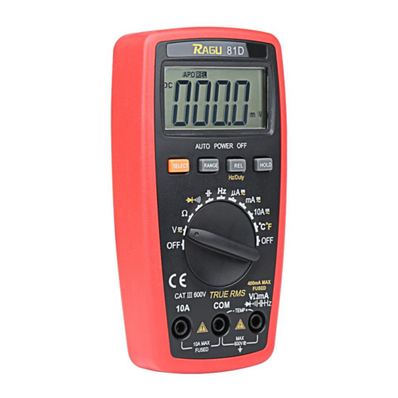
- Page 1 RAGU 81D DIGITAL MULTIMETER OPERATION MANUAL...
-
Page 2: Table Of Contents
Contents I. General...........- 1 - Ⅱ. Open-package Inspection....- 2 - III. Safety Considerations......- 3 - IV.Instrument Panel & Button Function Description..........- 9 - V. Other Functions........- 12 - VI、Property...........- 13 - 1.General Property ......- 13 - 2.Technical Property....- 14 - 2-2-1. -
Page 3: General
I. General The RAGU 81D digital multimeter, equipped with the LCD display of text height 18.9mm, is a 3 3/4 digital multimeter which has merits of clear reading, stable performance and high reliability. It could be used to measure DC voltage,... -
Page 4: Ⅱ. Open-Package Inspection
switching and a digital display drive offering high resolution and high precision. Due to its complete functions, high measurement accuracy and convenient operation, the multimeter is the ideal tool in laboratory and factory as well as for radio fans and family. Ⅱ. -
Page 5: Safety Considerations
AAA (1.5v) 7# batteries 2 PCs III. Safety Considerations The design of meter is in accordance with IEC1010 clause (the safety standard issued International Electrotechnical Commission). Prior to the operation of the instrument, please read safety considerations first. 1. When DC voltage is higher than 30V, AC voltage is higher than 25V, current is higher than 10mA, AC power line with inductive load or power line during electric... - Page 6 correct position. Check if the test lead is contacted reliably, connected correctly, and grounded well and etc. in order to avoid electric shock. 3. Only if the meter is used with the matched test lead, can it meet the requirements of safety standard.
- Page 7 terminal. Don’t other unconfirmed disapproved batteries replace batteries inside the meter. Only the batteries of the same model or same electrical specification can be replaced. Before the replacement, the test lead must leave the measuring point and ensure there is no any signal at the input terminal. 6.
- Page 8 Don’t store high-temperature, high-humidity, inflammable environment strong magnetic field. It may cause damage to the meter and endanger the operator’s safety if you take any voltage measurement that exceeds the limits. The ultimate voltage value permitted for measurement is marked on instrument panel.
- Page 9 measurement to prevent damaging the endangering the operator’s meter and safety. 10. Don’t try calibrating or repairing the meter. When necessary, only the qualified professional personnel who have had special training or gained approval can make it. 11. During measurement, the requirement of measurement function must...
- Page 10 switch during measurement. 12. When “ ”is shown on LCD display, please replace battery immediately to ensure the measurement precision. 13. It is not allowed to insert the test lead into the current terminal to measure voltage! Please don’t change the circuits of the meter by yourself to prevent damaging endangering meter...
-
Page 11: Description
IV. Instrument Panel & Button Function Description 1. Instrument Model Number 2.LCD Display: Display the measured data and unit. 3. Function 400mA MAX FUSED Button 3.1.SELECT(function switch):Press this button, the function could switch between DC/AC/ - 9 -... - Page 12 3.2.RANGE(auto/manual range switch): The meter is in automatic range when starts up, press the “RANGE” button to activate manual range mode. In the mode of manual range, each press lets the meter skip to the previous shift. When it goes to the highest shift, it goes back to the lowest shift automatically.
- Page 13 3.4 REL (Relative Value Measurement): The relative value measurement of all functions could conducted pressing this button except the Hz/Duty function. Frequency/duty cycle: press this button to select frequency or duty cycle measurement mode. Function/Range Selection Switch : It could be used to change the measurement function and range.
-
Page 14: Other Functions
5.3.Voltage、Diode、Resistance, Capacity, Frequency, Buzzer, Temperature and “ +” Input terminal with current less than 400mA. V. Other Functions Automatic Power off During measurement, meter will automatically shut down (enter sleeping mode) to save power if function buttons and function/range selection switch are not operated in 15 minutes. -
Page 15: Property
SELECT button to turn on the instrument. VI、Property 1.General Property 1-1. Display:LCD 1-2. Max Display : 3999 ( 3 3/4 ) counts automatic polarity display and unit display 1-3. Measuring Method : Dual integral A/D converter 1-4. Sampling Rage:Approx. 3 times / sec. 1-5. -
Page 16: Technical Property
Relative Humidity: <80% ; 1-9.Power: 2pcs 1.5V batteries (“AAA”7# battery) 1-10.Dimension (size): 145×74×36mm 1-11.Weight: Approx. 190g(Including 2pcs 1.5V batteries) 1-12.Accessories: Instruction Manual (1 pc), Holster (1 pc), Outer packing box (1 pc), 10A test leads (1 pair), K-Thermocouple and 1.5V batteries (2 pcs). 2.Technical Property 2-1. -
Page 17: Dcv
2-2-1. DCV function/range selection switch 1. Turn the to " " Range; 2. The initiate state of the meter is in automatic range status, which shows "AUTO" symbol; 3. Make the test leads contacted to the testing points. The voltage and polarity of the point where the red test lead is contacted will be displayed on the screen. -
Page 18: Acv True Rms
high voltage circuit. Range Accuracy Resolution 400mV 100uV ±(0.5%+4d) 10mV 400V 100mV 600V ±(1.0%+4d) Input Impedance: 400mV>40MΩ; 10MΩ at other Ranges. Overload Protection: 600V DC or 600V AC Peak Value. 2-2-2. ACV True RMS 1. Insert the black test lead into the hole of “COM”... - Page 19 press “SELECT” button to select the AC measurement mode. 3. The initiate state of the meter is in automatic range status, which shows “AUTO" symbol; 4. Make the test leads contacted to the testing points. The voltage of the point where the red test lead is contacted will be displayed on the screen.
-
Page 20: Dca
Range Accuracy Resolution ±(0.8%+6d) 10mV 400V 100mV 600V ±(1.0%+6d) Input Impedance: >10MΩ; Overload Protection: 600V DC or 600V AC Peak Value; Frequency Response: (50~200) Hz; Display: Average value response (RMS of sine wave). 2-2-3. DCA 1.Insert the black test lead into the "COM" input terminal and red one into the "... - Page 21 terminal (Max 10A). 2. Rotate function switch to Current gear. The initiate state of the meter is in automatic range status, which shows "DC" symbol. Then connect the test leads to the tested circuit in serial, the tested current value and the current polarity of the point where the red one is contacted will be displayed on the screen simultaneously.
-
Page 22: Aca True Rms
Range Accuracy Resolution 400uA 0.1uA 4000uA ±(1.0%+10d) 40mA 10uA 400mA 100uA ±(1.2%+10d) 10mA Max measurement voltage drop: Full Range mA is 0.4V, A is 100mV; Max input current: 10A (less than 15 seconds); Overload Protection: 0.4A/250V restorable fuse, 10A/250V fuse. 2-2-4. - Page 23 10A input terminal (Max 10A). Rotate function switch to Current gear. Press “SELECT” button to select the AC measurement mode. Then connect the test leads to the tested circuit in serial, the tested current value and the current polarity of the point where the red one is contacted will be displayed on the screen simultaneously.
- Page 24 current will lead to fuse melt or even damage the meter. Range Accuracy Resolution 400uA 0.1uA 4000uA ±(1.5%+10d) 40mA 10uA 400mA 100uA ±(2.5%+15d) 10mA Max measurement voltage drop: Full Range mA is 0.4V, A is 100mV; Max input current: 10A (less than 15 seconds); Overload Protection: 0.4A/250V restorable fuse,10A/250V fuse;...
-
Page 25: Resistance (Ω)
2-2-5. Resistance (Ω) 1. Insert the black test lead into "COM" terminal and red one into " " terminal. 2. Rotate the Range to “Ω” gear. Cross connect the test leads to the tested resistor. 3. When measuring the low resistance, please short-circuit the test leads at first to test the wire resistance, and then deduct it from the actual resistance. - Page 26 measuring the high resistor. 2. When the input terminal is open circuit, it will display “OL”. 3. When measuring in-line resistor, be sure that the power is off and all capacitors are discharged completely. Range Accuracy Resolution 400Ω ±(0.8%+5d) 0.1Ω 4kΩ...
-
Page 27: 2-2-6.Diode And Continuity Test
Note: When measuring at Range 400Ω, please short-circuit the test leads at first to test the wire resistance, and then deduct it from the actual resistance. 2-2-6.Diode and Continuity Test 1. Insert the black test lead to “COM” terminal and the red one to “ ”... - Page 28 the black one to the diode negative polarity. The approximate value of diode forward voltage drop will show on the display. 4. Backward Measurement: Connect the red test lead to the diode negative polarity and the black one to the diode positive polarity. "OL"...
- Page 29 less than 50Ω. Range Display Test Condition Forward DC Forward Current is Approx. Voltage Drop 0.5mA, Backward of Diode Voltage is Approx. 1.5V Buzzer makes Open circuit a long sound voltage is Approx. if resistance is 0.5V less than 50Ω Overload Protection: 250V DC or AC Peak Value.
-
Page 30: Capacity (C)
2-2-7. Capacity (C) 1. Rotate function switch to " " gear; 2. Insert the black test lead to “COM” terminal and red one to " " terminal; 3. Connect the tested capacity by the test leads to “COM”, " " input terminals, screen will show... -
Page 31: Frequency (F)
reading at 1000uF Range. Accurac Range Resolution ±(5.0%+90) 1 pF 40nF 10pF 400nF 100pF ±(4.5%+8) 4μF 40μF 10nF 100μF ±(5.0%+8) 100nF 1000μF ±(5.0%+8) 1μF Overload Protection: 250V DC or AC Peak Value. 2-2-8. Frequency (F) 1. Connect test leads and shielded cable to ”... - Page 32 Connect test leads and the cable to the signal source or the tested load. The tested signal will show on the screen. Caution: 1. When inputting AC RMS over 10V, it could show reading, but excess vibration may appear; 2. It is recommended to test weak signals by shielded cable under noisy circumstances.
-
Page 33: Temperature (℃/℉)
0.001Hz 10Hz 0.01Hz 100Hz 0.1Hz 1kHz ±(0.5%+10) 10kHz 10Hz 100kHz 100Hz 1MHz 1kHz 30MHz 10kHz For your 0.1-99.9% 0.1V reference Input Sensitivity: >1VRMS , Overload Protection: 250V DC or AC Peak Value. 2-2-9. Temperature (℃/℉) 1. Rotate function switch to (℃/℉)gear. 2. - Page 34 jack and anode into “ ” terminal. Then working (temperature measurement end) of thermocouple on the surface or inside the object to be tested. Then you can read temperature from the screen, and the data is in Centigrade. Caution: 1. When the input terminal is open-circuit, it will display the normal temperature.
-
Page 35: Instrument Maintenance
<400℃± (-20 ~ (1.0%+5d) 1℃ 1000)℃ ≥400℃± (1.5%+15d) <750℉± ~ (0.75%+5d) 1℉ 1832)℉ ≥750℉± (1.5%+15d) Sensor: Type Thermocouple (Nickel-chromium--nickel silicon) (banana plug). CAUTION: DO NOT INPUT VOLTAGE AT THIS RANGE! VII. Instrument Maintenance This is a precision instrument and the user shall not modify the electric circuit at will. - Page 36 1. Keep the instrument away from water, dust and shock. 2. Do not store and operate the meter under the condition of high temperature, high humidity, combustible, explosive environment and strong magnetic field. 3. Wipe the case with a damp cloth and detergent;...
- Page 37 5-1. Loosen the screw on the back cover that secures the battery door and exit the battery door; 5-2. Remove 1.5V batteries and replace them with two new ones. Although a 1.5V battery of any standard can be used, but in order to extend the operation life, alkaline batteries should be used;...
-
Page 38: Fault Elimination
3. Don’t use the instrument when the battery has not been installed properly or the back cover has not been tightened. 4. Prior to the replacement of battery or fuse, please remove the test leads from the measuring points and switch off the meter. VIII. - Page 39 Fault Solution ● Turn on power; No Display ● Replace battery. ● Replace battery. symbol appearance Inaccurate ● Replace battery. measuring values This Instruction is subjected to change without any further notice. The content of this Instruction is considered correct, and in case readers find any errors and missing parts, please contact the manufacturer.
- Page 40 function elaborated this Instruction shall not be taken as the reasons for using the product for special purposes. - 38 -...
Need help?
Do you have a question about the 81D and is the answer not in the manual?
Questions and answers