Advertisement
Identification
Manufacturer
EOS Saunatechnik GmbH Schneiderstriesch 1
35759 Driedorf, Germany
Tel.: +49 2775 82-0
Email: info@eos-sauna.com
Identification
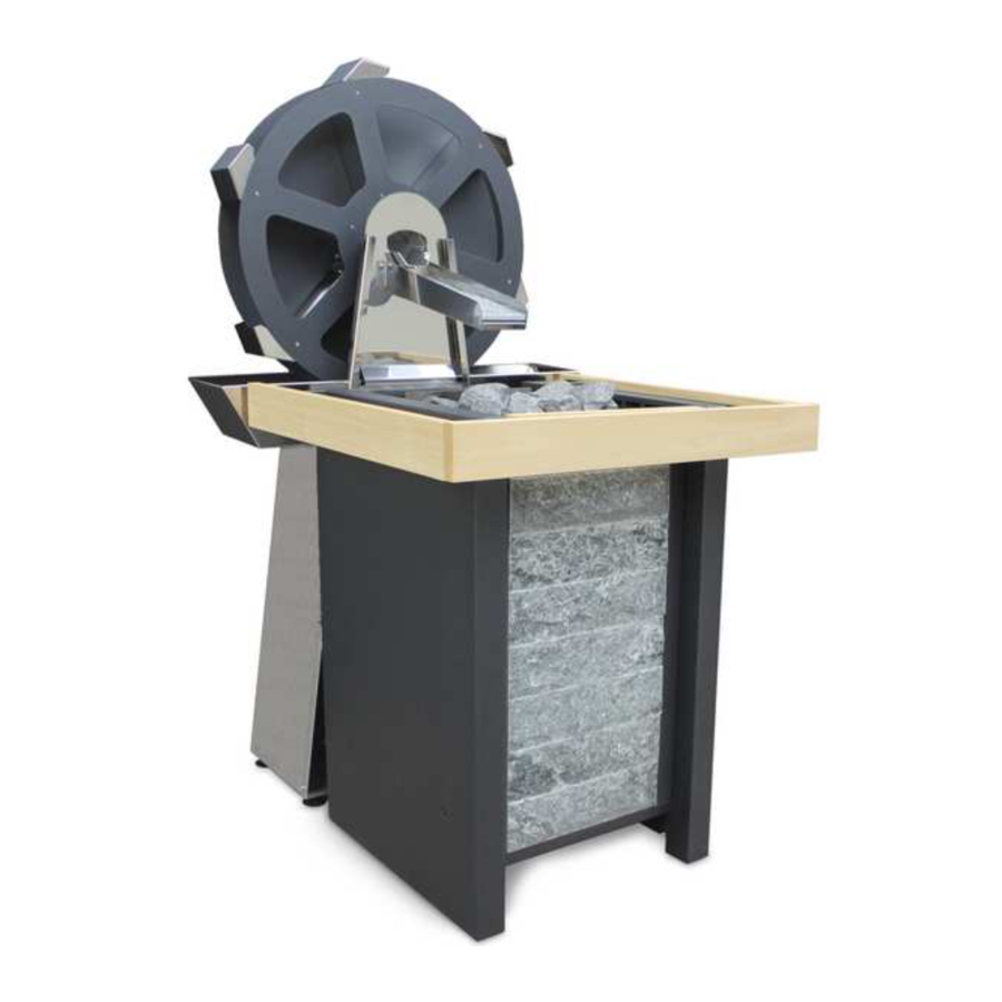
The EOS mill wheel is an electrical device for automatic infusion on a corresponding sauna heater.
The EOS mill wheel may only be operated in conjunction with an EOS control unit, which is included in the delivery contents.
Nameplate
The nameplate is attached on the rear side of the heater.

- General name
- Model name
- Item number
- Electrical connection
- Approval symbols
- Country of origin
- Manufacturer
- Date of production
- Serial number
Intended use
This device is intended exclusively for automatic infusion in a sauna in conjunction with a sauna heater, either EOS Herkules S60 or EOS Stone S60, 9, 12 or 15 kW and a control unit, which is included in the delivery contents.
EOS Mill Wheel is a floor-standing device. It is suitable for cabins for commercial and private use.
The device consists of separate components - such as the stand with the pillar, the "mill" unit itself, water tank, cascade and separate control unit.
![]() The heater is not suitable for outdoor use.
The heater is not suitable for outdoor use.
It must be operated only in sauna cabins and may not be exposed to environmental conditions such as extreme humidity and moisture or the possible formation of condensation or corrosive substances in the ambient air, as well as other weather conditions. The control unit may only be installed outside the sauna!
Any use beyond this is considered improper use. Proper use also includes compliance with operating, maintenance and servicing requirements.
- The unit is operated without knowledge of or compliance with the safety instructions.
- Operating, service and maintenance requirements are not observed.
- The unit is operated by children under 8 years of age.
- The unit is operated by children 8 years of age or older, or persons with reduced mental capacity who have not been thoroughly instructed in its use.
- The control unit is installed inside the sauna.
- The device is not used with a compatible heater.
Scope of delivery
Check the delivery to ensure that all components were delivered and that the unit is in proper working order. Contact your distributor if components are missing or damaged. The unit must not be operated if components are missing or damaged.
The following parts are included in the scope of delivery:
- Stand with column
- Mill wheel
- Water tank
- Cascade
- Control unit
- Accessory bag
- Installation and Operating Instructions
Accessories (optional)
| Accessories | Item no. |
| Remote control button | 94 4087 |
Technical data
| Electrical connection | 230 V ~ 50/60 Hz |
| Output | 5W* |
| Motor data | max. 60V DC, max. 2A, 20Nm |
| Weight, without packaging | 39 kg |
| Dimentions, H x W x D | 150 x 80 x 66 cm |
| For use with the control units | Control unit (included in the delivery contents) |
| For use with the sauna heater | EOS Herkules S60 or EOS Stone S60 9,12 or 15 kW |
| IP protection | IPx4 |
| Water connection | ¾" |
| Water pressure | 0.3 - max. 10 bar |
| Light | 230V, max. 2.5 A, N/O contact |
| Fan | 230V, max. 2.5 A, N/O contact |
* plus the power consumption of light and/or fan.
Installation
This chapter shows how to install the mill wheel together with a compatible sauna heater.
General installation instructions for the installation
All electrical installations laid inside the cabin must be suitable for silicone cables and a temperature of at least 140°C. A 4-core heat-resistant cable is required for the connection (included in the delivery contents).
All lines must be routed in such a way that they are well-protected, e.g. in a cable duct. EOS recommends laying all connecting cables through a bendable metal tube connected to the protective conductor.
NOTICE
The control unit may only be installed outside the sauna!
NOTICE
The mill has a fixed water connection and requires a permanent water supply.

Fire hazard
Prior to the installation of all individual components all protective foils must entirely be removed.
Specifications for theinstallation
- Installation site
- Ceiling height of at least 190 cm
- Distance device – cabin wall 10 cm.
- Dimensions and safety gaps


- Mill wheel
- Water tank
- Stand with column
- Fixed water connections
- Cascade
Installing a mill wheel with the sauna heater
The device is supplied packaged on a pallet.
- Align mill
Put the stator with the column onto the desired place and align horizontally by means of the plate feet.
Use a water-level as supporting instrument.


- Stator
- Plate feet
- Water-level
- Install Cascade
The cascade is screwed tight with 2 screws.
![warning]() ATTENTION! Tighten the two screws firmly.
ATTENTION! Tighten the two screws firmly.


- Fastening screws
- Cascade
Install water tank

- Water tank
- Insert water tank sideways.
NOTICE! Consider position of shovel. - Mediate the water tank.
- Place sauna heater
- Place the sauna heating unit (Herkules S60), as shown next in front of the mill wheel as shown
- Place the inlet channel over the stone basket, so that the cascade ends centrally above the channel. The 4 noses on the underside of the inlet troughnengage in recesses in the stone basket frame. This prevents the gutter from being inadvertently of the inlet channel is impossible.


- Mill wheel
- Cascade
- Inlet channel
- Sauna heater
- To ensure an even distribution of the water even distribution of the water, align the gutter with the water-level

- Water-level

Set up fixed water connections
NOTICE
Contaminaton of drinking water
The regulations of EN 1717 and/or DIN 1988 Part 4 must be attended. Appropriate measures must be taken that prevent the water from running back into the drinking water pipeline. For this, especially pipe isolators or system isolators are appropriate.
- If necessary, ask your drinking water supply company or your local sanitary expert.
Connect fixed water connection with water system on-site.
NOTICE
Between fixed water system and fixed water connection a shut-off cock must be installed.
- In case the fixed water connection will not be used for any length of time, the shut-off cock is to be closed.
- The stopcock allows the water supply to be quickly disconnected for maintenance and repairs.
- Maximum operating pressure 10 bar


- 3/4" connection nipple for fixed connection on site.
- Finished connection fixed water connection - water tank
Fill with water

- The system may only be filled with water.
- The water level in the water tank should be between 70 and 110 mm.
- Design overview
The float (G) opens or closes the valve (C) to ensure that the tank remains full.
The water level can be regulated by turning the float.
A hose nozzle can be attached to the overflow protection (F), through which any overflow water can be drained on site.


- Reducing sleeve from ¾" to ½"
- Seal ¾"
- Valve with ¾" connection option
- Float lever
- Mounting bracket
- Overflow protection ½"
- Float
![]()

Installing a control unit
- Mount the control unit outside of the cabin.
- To this end, open the housing and fit to the intended place with four screws.
- Lay the fed line to the mill wheel and connect it to the motor connection on the rear of the mill wheel.
- Remove the mill wheel plug (A) and the control unit plug (B).
- Connect the two plugs to each other.
- Close the lever lock.


- Mill wheel plug
- Control unit plug
- Lever lock
Electrical installation
General instructions for electrical installation
- Inappropriate installation or usage could cause fire hazard! Please read this mounting instructions carefully. Pay attention to all measurement specifications and the following notes.
- The mill wheel must only be used in connection with the sauna heating device EOS Herkules S60 or EOS Stone S60 9,12 oder 15 kW and the associated sauna control unit.
- The device has been designed for a connection voltage of 230 V AC.
- The installation and the connection of the device and other electrical utilities must only be carried out by trained technicians. Here, it is especially important to abide by all protective measures necessary according to VDE 0100v. §49DA/6 and VDE 0100 Part 703/2006-2
- The mill-sauna will be connected to the power supply system via an earthed plug. All connecting lines to be passed inside the cabin must be suitable for an ambient temperature of min 140 degree. We recommend a silicone line. If single-wired lines will be used as connecting lines, they must be protected by bendable metal pipes ƒ
- Please see that the control unit is located outside the cabin.
The electrical installation must be performed by authorised electricians only.
The provisions of your public utility and the relevant VDE provisions (DIN VDE 0100) must be observed.
Beware, danger of life: Never perform repairs and installations yourself. The housing must only be removed by an expert.
All wires of the system must be dis connected from the mains during installations and repairs, i.e. fuses or main switches must be deactivated.
The security and installation notes of the sauna oven manufacturer must be observed.
Establishing an electrical connection

- Control unit
- Remote control button (optional)
- Control unit connections


- DIP-switch
- Terminals for light and fan
- Terminals for mains 230V
- Main switch ON/OFF
- Cable glans (drive / mains / light and fan)
- Terminals for the external push-button
- Terminals for the drive
- Connection diagram


Remote control button (optional)

NOTICE
Installation location - only outside the cabin.
Wall mounting

- Preferably chose the outside wall of the cabin for mounting.
- Cut the two adhesive tape strips supplied into two equally long parts (40 x 20 mm).
- Now fit the two adhesive tape strips at the rear of the button housing at the same distance.
- Press the button housing with the affixed adhesive tape against the wall in the desired place of mounting.
- Now pull the button back off again and press the remaining adhesive tape strips down.
- Then affix the button again and lead the connection line to the controls
Electric connection of the button

- Feeder line Remote control button
Commissioning
The settings for water splash events are made with the DIP-Switch on the main board.
 ATTENTION: Make settings (DIP-Switch) only with the system disconnected from power!

- Position ON
- Position OFF
![]() DIP-Switch
DIP-Switch
 DIP-Switch
- Settings for the number of splashes and time intervals

![]() DIP-Switch - complete overview of settings
DIP-Switch - complete overview of settings - Switching to an external push-button
Using the DIP-switch no. 5 you can set the operation control to be made from an external push-button.- Switch 5 „ON" - control from an external push-button. Settings made with switches 3 and 4 remain inactive.
- Switch 5 „OFF" - time intervals will be controlled as per settings of the switches 3 and 4, as indicated in the general table.

 DIP-Switch - complete overview of settings
NOTE
Only switch the mill on when the heater and sauna stones are at operating temperature. This takes approx. 45 minutes.
Switch the mill wheel on using the ON/OFF switch.
The programme procedure starts.
To use an optional remote start button, DIP switch 5 must be set to ON.
After every infusion, wait approx. 10 minutes until the next infusion. Only then have the sauna stones heated up properly.
- Light and fan
The light and fan are N/O contacts.
As soon as the connection is established, they function as follows:- The light is switched on approx. 1.5 minutes before an infusion cycle.
- After each infusion cycle, the fan switches on after a time delay of approx. 5 seconds for a duration of approx. 20 seconds.
- After the last infusion of a cycle and the fan operation, the light switches off together with the fan.
Maintenance
- Adjusting the drivebelt tension
- First loosen the four mounting screws (B).
- Adjust the drivebelt tension using the adjustment screw (A).
NOTICE! The drivebelt may be compressed by a maximum of 5 mm under light pressure. - Finally, tighten again the four adjustment screws (B) of the motor.
- The Watermill wheel, blades and cascade must be cleaned of limescale residues at least once a week.


- Adjustment screw
- Mounting screws
![]() Motor with drivebelt
Motor with drivebelt

General safety instructions
Safety levels
Safety instructions and important operating instructions are classified. Please familiarise yourself with the following terms and symbols:
Indicates a hazardous situation which, if not avoided, could result in death or serious injury.

Indicates a hazardous situation which, if not avoided, could result in minor or moderate injury.
Notice
Indicates a hazardous situation which, if not avoided, will result in damage to the unit.
Mounting and electrical installation
 These installation instructions are intended for qualified personnel familiar with the laws and regulations applicable to electrical installations at the installation site. Observe the following general safety instructions during mounting, configuration and commissioning of the product.
- Risk to life and limb and risk of fire
Risk to life and limb from electric shock and fire in the event of improper or faulty electrical connection. This risk remains also after completion of the installation work.- The electrical installation of the heater, relay boxes and other electrical systems or equipment with a fixed mains connection must only be performed by a trained electrician from an authorised electrical company.
- Ensure compliance with the locally applicable standards and regulations for electrical installation.
- The system must be completely disconnected from the mains supply before commencing installation and repair work.
- The housing cover must only be removed by a specialist.
Operator instruction
The operator of the sauna cabin must be instructed in the general safety instructions during commissioning. The operator must be given a copy of the operating instructions.
- Risk of electric shock
A risk to life and limb from electric shock and fire arises in the event of improper repair work. This risk remains also after work is completed.- The housing cover must only be removed by a specialist.
- Repairs and installations must only be performed by a trained specialist.
- The system must be disconnected and removed entirely from the mains supply before commencing repair work.
- Use only original spare parts from the manufacturer.
- Operation by children or persons with reduced mental capacity
This unit should not be used by children or persons with reduced mental capacity or limited physical or sensory abilities. Children must not play with the unit.- Children or persons with reduced mental capacity, or limited physical or sensory abilities must be supervised to ensure they do not play with the unit.
- Children under 8 years of age should not operate the sauna cabin.
- The settings for the heating time must only be changed by children under 8 years of age if they are supervised by an adult.
- The sauna cabin must only be used by persons with reduced mental capacity, or limited physical or sensory abilities under supervision or if they have been previously instructed in its use and understand the risks.
- Children and persons who have not received proper instruction must not clean or service the system.
Service Address
EOS Saunatechnik GmbH
Schneiderstriesch 1
35759 Driedorf
Germany
Tel: +49 (0)2775 82-514 Fax: +49 (0)2775 82-431 servicecenter@eos-sauna.de www.eos-sauna.de
Documents / Resources
References
Download manual
Here you can download full pdf version of manual, it may contain additional safety instructions, warranty information, FCC rules, etc.
Advertisement


Need help?
Do you have a question about the Mini and is the answer not in the manual?
Questions and answers