Advertisement
Quick Links
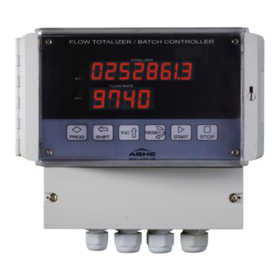
FLOW INDICATOR
TOTALIZER
MODEL: MX-450W
DESCRIPTION
The ASHE MX-450W is a micro-controller based Digital Flow Rate
Indicator Totalizer with Batch Control function, offered in a compact,
rugged and reliable execution.
The instrument has two LED digital displays on the front panel – the Rate
Display and the Totalizer display. The
value on a four-digit display (upto 9999 units) while the
indicates the accumulated flow integrated over the selected time scale on
an eight-digit display (upto 99999999 units). The instrument has non-
volatile memory (i.e., in case of power failure, the last totalized value is
retained in memory and the integration resumes after power is restored.
The instrument accepts a standard analog input signal of 4 to 20 mA DC
(two/four-wire) or a Pulse (Frequency) input of 0-10 kHz. An auxillary
power supply of 24 VDC @ 100 mA is generated internally and is
available for powering the external Transducer or Mass Flow Meter. The
input signal to the instrument is suitably isolated and conditioned by the
micro-controller, which displays the flow rate in real time on the Rate
(lower) display.
At the same time, it integrates this signal with respect to the selected
time scale and displays it on the Totalizer (upper) display. The Totalizer
display can be reset to Zero (00000000) by pressing the Reset button for
a continuous duration of five seconds. This feature has been provided to
prevent any accidental erasure of the totalized value.
Two Relay outputs are offered – each of which may be independently
configured to activate at either the flow rate value or the batch totalized
value, as desired – these set points may be set through the Membrane
Switch-pad on the front panel [see
indications show the over-range status of the two control Relays.
The Flow Indicator Totalizer Model MX-450W operates on Universal AC
power supply from 90 to 270 VAC mains supply, unless specified
otherwise. It is available in field-mounting (weather-proof / explosion-proof
executions) and standard panel mounting enclosures.
INSTALLATION
The instrument should be first mounted in it's cut-out with the help of the
Mounting Clamps provided. All interconnections to the instrument should
be made with strong multi-strand wire of the order of 2.5 sq.mm. The
ends of the wires should be properly ferruled and suitable lugs must be
used for effective termination.
The cables carrying the input signal should be routed separately and
properly isolated from the power line cables to prevent any electro-
magnetic interference in the input signal readings from the mains power
line. Use of shielded twisted pair cable is recommended for input signals.
The shield must be connected to Earth at the instrument end. The
instrument should be earthed to a proper grounding point before
connecting the Power Supply. The voltage between the Earth and Neutral
terminals should be negligible (Approx. 1 VAC). The Relay contacts are
potential free and any desired voltage may be switched.
display indicates flow rate
RATE
display
TOTALIZER
S
section].
Two LED
ETTINGS
CONTROL KEYS
The instrument has six keys on the front panel, the functions of which
are described below :
The PROG or PROGRAM key is the central co-ordinating key
to access the settings of the instrument. Pressing this Key
PROG
allows the operator to sequentially view, change and save the
parameters such as Zero and Span settings, Decimal Points
for the totalized and rate displays, Relay Set-points for batch-
control and process control, Hysterisis, Time Scale, etc.
The SHIFT key allows the operator to shift the display during
SHIFT
setting to the left by one digit per activation. This key should be
used in conjunction with the INC (incrementing) key to set the
desired control parameters.
The INC or Incrementing key allows the operator to select the
numeral in the digit being set. The digit will sequentially display
0, 1, 2.... 9 on each pressing of the INC key. This may be used
INC
to set the Zero/Span and Set points of the Batch and Rate
displays.
The RESET key allows the operator to reset the totalized value
on the eight-digit display to "00000000" so as to restart the
integration process. The RESET key should be pressed for a
RESET
continuous duration of five seconds to achieve the resetting.
This is specifically provided to avoid any accidental erasure of
the totalized value.
The
START
START
Simultaneously, it resets the Relays, if they happen to be in an
alarm condition.
The STOP key stops or temporarily pauses the counting
STOP
process. Also, if the STOP key is pressed while the Totalizer is
operating in normal range, then the Relays are de-energized.
TECHNICAL SPECIFICATIONS
Model
: ASHE MX-450W.
Type
: Microcontroller based Digital Flow Indicator
Totalizer.
Input Signal
: 4 - 20 mA DC / Pulse (frequency).
: Seven-segment ½" red LED display.
Display
Indications
: Four-digit for Flow Rate display.
Eight-digit for Totalizer display.
Rate Scale Range
: 0 to 9999
Totalizer Scale Range : 0 to 99999999 [eight-digit].
Decimal point
: Selectable for both displays.
Output Signal
: 4 to 20 mA DC retransmitted [O
Load Driving capacity : Upto 600 Ohms.
Response time
: Typically 100 mS to within one count of the final
value.
Output
: Two control relay change-over contacts.
Contact rating
: 10 Ampere @ 230 V AC (Res. Loads).
: 0.1% FS.
Accuracy
Power Supply
: 90 to 270 V AC, 50 / 60 Hz ( 5%).
Auxillary Power supply :24 V DC @ 100 mA for Transmitter.
Dimensions
: 166 (L) x 161 (W) x 121 (D) mm.
Enclosure
: Industrial grade ABS.
Ambient temp.
: 0 to 60
Execution
: Wall mounting.
Key
initiates
the
counting
process.
[four-digit] configurable.
PTIONAL
O
C.
].
Advertisement

Related Manuals for ASHE MX-450W


Summary of Contents for ASHE MX-450W
- Page 1 “00000000” so as to restart the integration process. The RESET key should be pressed for a The ASHE MX-450W is a micro-controller based Digital Flow Rate RESET continuous duration of five seconds to achieve the resetting.
- Page 2 0000 / (If input signal is not connected) 00000000 Upon switching on the power, the display shall show “ --- ASHE --- “ for three IPLO ** IPLO indicates input signal is below 4mA seconds on the RATE (lower) display and then display the last totalized value...
- Page 3 totalizing process and allow the user to make any desired changes. Also, if the Minute / Hour / Day). Hence for a Flow Rate of 0 to 5600 kg/Hour, totalized display needs to be RESET, then the STOP key must be pressed first. the selection would be “Hour”.
- Page 4 TERMINAL DIAGRAM NO CONN NO CONN 90-270 VAC, 24 V DC 4-20mA DC 4-20mA DC CONN Relay-1 Relay-2 50/60Hz Aux. OUTPUT INPUT NOTE A DC) :- OR CURRENT INPUT Input signal must be connected to Terminals “17 & 18” (for four-wire configuration). For two-wire configuration, Transmitter Power (24 VDC @ 100 mA) is available on Terminal nos.
Need help?
Do you have a question about the MX-450W and is the answer not in the manual?
Questions and answers