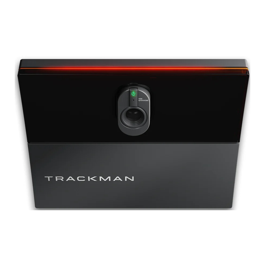
TrackMan iO Manual
- Installation instructions manual (20 pages) ,
- Installation instructions manual (41 pages)
Advertisement
- 1 GETTING STARTED
- 2 THE SPACE
- 3 MOUNTING TYPES
- 4 SETUP TYPES
- 5 INSTALLATION MOUNTING SETUP
- 6 MOUNTING TYPE A
- 7 MOUNTING TYPE B
- 8 POWERING UP YOUR TRACKMAN iO
- 9 CONNECTING YOUR TRACKMAN iO TO A PC AND THE INTERNET
- 10 INSTALLING TPS (9.2 OR LATER)
- 11 CONNECTING TO YOUR TRACKMAN iO
- 12 CALIBRATING YOUR TRACKMAN iO
- 13 MOUNTING SCREWS RECOMMENDATIONS
- 14 PLUGGABLE EQUIPMENT
- 15 UPDATES AND INSTALLATION VIDEO
- 16 Documents / Resources
GETTING STARTED
PACKAGE CONTENTS

- Trackman iO box
- Calibration board
- Trackman iO with protective foil and mounting plate
- Power cable (country specific)
- Power adapter
- Flashlight
- 4 pcs M6 12 mm screws for VESA 100x100 mount (NOT included) plus 2 pcs spare screws
- Tee
- Tee marker
- USB stick (contains safety and conformity guide, intallation instructions and software)
- 3 pcs AAA Battery
- Box contents and safety instructions
- Ceiling bracket (attached to Trackman iO)
DEFINITIONS
LH: Left hand
RH: Right hand
Target point: A spot or line that indicates the preferred aiming direction
TPS: Trackman Performance Studio (PC Software) adjustable drop pole/bracket)
EQUIPMENT NEEDED (NOT INCLUDED):
- Ladder
- Pen or pencil
- Portable drill with ceiling surface-specific drill bits
- 4 pcs 4 mm x 30 mm ceiling surface-specific screws
- 4pcs 6mm x 35mm raw plugs (wall anchors)
- Blanket or towel
- Ethernet cable (minimum Cat6/shielded)
- 2 golf clubs or alignment sticks.
- Screwdriver (choose standard or Phillips based on the screws you are using)
- Bubble level
If you are not mounting your Trackman iO directly to the ceiling using the attached ceiling bracket, you will require additional equipment:
- VESA mount (100x100, with rotary joint and adjustable drop pole/bracket)
- Plumb line (or laser level, or heavy-duty tape measure)
THE SPACE

- HITTING SURFACE Must be green in color. The center of the HITTING SURFACE must also be the center of the TEE AREA
- FLOOR SURFACE
- HITTING SCREEN
- CEILING SURFACE
- TEE AREA 60 x 40cm / 2´x 16" You will be able to hit shots from this TEE AREA the center of which is indicated by the tee marker


MOUNTING TYPES

- Direct ceiling mount
- See section for Mounting Type A installation process
- VESA mount (100x100, with rotary joint and adjustable pole/bracket)
- See section for Mounting Type B installation process
To ensure a functional system, select a mounting type for installing your Trackman iO:
- Use Mounting Type A (direct ceiling mount) when the distance between the HITTING SURFACE and the CEILING SURFACE is between 285 cm / 9'4" – 305 cm / 10'0" as listed in the Space requirements.
- If the distance between the HITTING SURFACE and CEILING SURFACE is greater than 305 cm / 10'0", use Mounting Type B VESA mount with adjustable pole/bracket set to the recommended mounting height of 295 cm / 9'8".

Whichever mounting type you choose, both the CEILING SURFACE and the floor must be level. Installing your Trackman iO on a CEILING SURFACE that is not level will affect its performance.
SPACE REQUIREMENTS
- Top of HITTING SURFACE to mounting height (i.e, where Trackman iO is attached to the CEILING SURFACE or VESA mount
Table 1 Mounting height of Trackman iO
| Mounting Height (cm) | ft/in | Comments |
| 305 | 10'00" | Max |
| 295 | 9'8" | Recomended |
| 285 | 9'4" | Min |
- TEE MARKER position to HITTING SCREEN or net. (Recommended minimum distance)
| Distance (cm) | ft/in | Comments |
| 250 | 8'2" | Min |
SETUP TYPES
- Projector and HITTING SCREEN setup
- Image projected on HITTING SCREEN in front of player.
- PC screen and net setup
- Image shown on separate monitor away from net.
Both mounting types can be used for either setup type A or B.
INSTALLATION MOUNTING SETUP
PREREQUISITES
Keep the protective foil on your Trackman iO and do not insert the power cable until instructed.
MOUNTING TYPE A
INSTALLATION PROCESS
- Place the tee marker at the preferred tee/ball position on the HITTING SURFACE at least 250cm/8'2" from the HITTING SCREEN/net. If your HITTING SURFACE allows, use the provided tee to fix the position of the tee marker.
![]()
Do not remove the tee marker until the entire installation process is complete. - Install the 3 AAA batteries in the flashlight and turn it on.
![]()
Do not look directly into the light cone. - Push the rear end of the flashlight into the flashlight bracket of the calibration board until it stops.
![]()
- Set the calibration board on the HITTING SURFACE with the tee marker you placed in Step 1 in the center. The side with the flashlight should be facing the HITTING SCREEN/net.
Using two golf clubs or alignment sticks on each side of the calibration board, align the calibration board with the preferred target point on the HITTING SCREEN/net.
Typically, the target point is the vertical center of the /net.
![]()
The flashlight beam now indicates where your Trackman iO should be positioned at your CEILING SURFACE. - Climb the ladder and use the pen/pencil to draw an "X" on the CEILING SURFACE in the center of the flashlight beam.
![]()
Have a person assist by supporting the ladder for safety.


- Now pick up the calibration board/flashlight from the floor and flip it so that the pattern is facing the floor.
Hold the calibration board against the CEILING SURFACE so that the X you drew in Step 5 is positioned in the center hole. Make sure the calibration board is parallel to the HITTING SCREEN/net. The tee marker you placed in Step 1 should be in the center of the flashlight beam.
![]()
Do not remove the tee marker until instructed.
- Use the pen/pencil to mark the four mounting holes in the calibration board on the CEILING SURFACE.
![]()
- Remove the calibration board from the CEILING SURFACE and turn off the flashlight.
- Choose appropriate drill bit size for your raw plugs/wall anchors and drill four holes. (Eg. concrete ceiling)
- Insert a raw plug/wall anchor in each of the drilled holes.
- Gently place your Trackman iO onto a blanket or towel with the back of the device facing up.
![]()
![]()
Do not remove the protective foil on the front cover until instructed.

- Remove the ceiling bracket from the back of your Trackman iO by simultaneously pressing the two release buttons/pins on each side of the bracket housing.
- Mount the ceiling bracket on the CEILING SURFACE using four screws and the pill-shaped slots. Before tightening the screws, adjust the bracket as needed to make sure it is mounted parallel to the HITTING SCREEN/net. Do not overtighten.

- Using both hands, mount your Trackman iO by lifting it at an angle toward the ceiling bracket and pushing it lightly in place until you hear a click. Do not let go of the unit until you are sure the lock has engaged.

-
Now it's time to complete the installation. Skip ahead to the "Powering up your Trackman iO" section.


MOUNTING TYPE B
INSTALLATION PROCESS
BEFORE YOU BEGIN: The following steps will show you how to use your preferred tee marker location to determine the proper position of the VESA mount (100x100) on the CEILING SURFACE. For best results, the adjustable pole/bracket on the VESA mount should be set to the recommended mounting height of 295 cm / 9'8". Please read these instructions carefully and double-check your measurements to ensure they are within the guidelines.
RECOMMENDED: This process is best performed by two people.
- Place the tee marker at the preferred tee/ball position on the HITTING SURFACE at least 250cm/8'2" from the HITTING SCREEN/net. If your HITTING SURFACE allows, use a tee to fix the position of the tee marker.
![]()
Do not remove the tee marker until the entire installation process is complete. - Set the calibration board on the HITTING SURFACE with the tee marker in the center. Using two golf clubs or alignment sticks on each side of the calibration board, align the calibration board with the preferred target point on the HITTING SCREEN/net. Typically, the target point is the vertical center of the HITTING SCREEN/net.
- From the center of the tee marker, measure 102 cm / 3'4" in the direction of the target point on the HITTING SCREEN/net. Mark this spot with an X. This spot represents the center of the VESA mount that will be installed on the ceiling directly above.

![]()
Have a person assist by supporting the ladder for safety. - Now climb the ladder until you can comfortably and safely reach the CEILING SURFACE. Use a plumb line (see NOTE below) extending between the CEILING SURFACE and the HITTING SURFACE to identify the spot on the CEILING SURFACE directly above the X you marked in Step 3. Mark this spot on the CEILING SURFACE with an X.

 NOTE: A plumb line, also called a plumb bob, is a length of line or string with a weight attached to the bottom, usually with a pointed tip. It is used as a vertical reference line. You may also use a laser level. (If you do not have access to either of these tools, you may use a heavy duty tape measure; hold the end of the tape to the CEILING SURFACE, then extend the case to the HITTING SURFACE. If using this method, you should also use a level to ensure the tape is vertical.)

- Position the base of the VESA mount on the CEILING SURFACE so that the center of the adjustable pole extends from the center of the X you marked in Step 4. Attach the base of the VESA mount to the CEILING SURFACE following manufacturer's instructions.
- Adjust the pole on the VESA mount so that the bracket that attaches to your Trackman iO is set to the recommended mounting height of 295 cm / 9'8" as shown in Table 2 (see NOTE below).
NOTE: Table 2 shows the relation between the mounting height and the proper position of the tee marker on the HITTING SURFACE. Please note that if the mounting height is higher or lower than recommended (but still within the guidelines), you may need to adjust the position of thetee marker slightly. If your Trackman iO is not installed according to the guidelines in Table 2, it may not function properly.
| Distance from center of tee marker to center of VESA mount | Mounting height (cm) /(ft/in) | Comments | ||
| cm | ft/in | cm | ft/in | |
| 105 | 3'5" | 305 | 10'0 | Max. |
| 102 | 3'4" | 295 | 9'8" | Reccomended |
| 98.5 | 3'3" | 285 | 9'4" | Min. |
Table 2 Distance from Tee Marker to center of VESA Mount
Have a person assist you fastening the 4 pcs M6 screws while holding the Trackman iO in both hands.
- Attach your Trackman iO to the VESA mount bracket using the supplied 4 pcs. M6 screws and tighten.


- Ensure the VESA mount is level
![]() and your Trackman iO is aligned with the HITTING SCREEN.
and your Trackman iO is aligned with the HITTING SCREEN.

POWERING UP YOUR TRACKMAN iO
- Once your Trackman iO is securely mounted, plug the ethernet cable into the ethernet port.

![]()
If your Trackman iO is mounted directly to the ceiling, use caution as there will be limited space when plugging in the ethernet cable.

- Connect the AC/DC power adapter to your Trackman iO.
- Connect mains powercable to AC/DC adapter.
- Place the adapter on the shelf of the Trackman iO
![]()
- Plug the DC connector into DC power plug on the side of Trackman iO
![]()
- Make sure the adapter is fastened to your Trackman iO by the Velcro strips.


Be sure to disconnect the AC/DC adapter before unmounting the Trackman iO.
- Now peel off the protective foils from the front and the lens ofyour Trackman iO. You can now also remove the tee marker from the TEE AREA.

- Connect the power plug from the AC/DC adapter into an appropriate outlet and your Trackman iO will turn on. The status indicator lights will display the current status as shown in Table 3.

| State | |
| Booting | Blinking green  |
| Ready (no PC connected) | Pulsating green  |
| Active (PC/TPS connected) | Solid green  |
| Recovery mode | Blinking green/red  |
| No Network connection | Blinking yellow  |
| Error | Blinking red  |
Table 3. The Trackman iO status indicator
YOUR INSTALLED SIMULATOR ROOM

Your Trackman iO must be oriented as shown above.
CONNECTING YOUR TRACKMAN iO TO A PC AND THE INTERNET

PC minimum requirements and recommended internet connection minimum upload/download. For further information visit https://www.Trackman.com/support
INSTALLING TPS (9.2 OR LATER)
- Ensure Windows is fully updated.
- Keep installing any pending updates and then press check for updates on the Windows Update settings page until no more updates are available. Reboot if necessary.
- Install the TPS version from the USB stick.
CONNECTING TO YOUR TRACKMAN iO
- Turn off any other Trackman device normally connected to the system to avoid TPS auto-connecting to it.
- Launch TPS and wait for it to load
- Click the Trackman logo at the bottom of the screen.
![]()
- You should be presented with a screen showing the Trackman iO as available.
![]()
- Select it.


- You may see a screen informing you about a license update to the device. Press OK.
- You should be presented with a screen informing you that a software update is available for the device.
![]()
- Press the button and wait while TPS downloads the required software to the computer.

CALIBRATING YOUR TRACKMAN iO
Your Trackman iO needs to be calibrated to know its position in the room relative to the TEE AREA and the HITTING SCREEN.
After connecting to your Trackman iO, you should be presented with a screen showing an image from one of the cameras in your Trackman iO.

If your Trackman iO has never been calibrated before it will show a view of the TEE AREA automatically
1: Do you see a view of the TEE AREA?
- No: Press "Calibrate"
- Yes: Proceed
2: Place the supplied calibration board on the floor and position it in the center of the image.
When placed correctly, you will see two crosses inside the hole in the board. The position of the hole indicates the optimal placement of the tee marker.

3: Press "Calibrate"
4: Pick up the calibration board and hold it against the HITTING SCREEN without covering the four corner markers on the calibration board. Now calibrate the distance from the TEE POSITION to the HITTING SCREEN.

5: Press the autotarget button and wait for TPS to locate the center of the HITTING SCREEN.
The following pattern will appear on one or more of your displays until TPS locates the correct one.

6: Press "Continue"
You should now be ready to use your Trackman iO with TPS.
MOUNTING SCREWS RECOMMENDATIONS
| Type | Diameter | Length | Environment |
| Screws | 4 mm | 30 mm | Ceiling mount Wood, plaster and concrete |
| Rawplugs | 6 mm | 35 mm | VESA 100x100 mount (Bracket) |
| Screws | 6 mm | 12 mm | VESA 100x100 mount (Drop pole) |
PLUGGABLE EQUIPMENT
The system can be used in both pluggable equipment type A. In both situations the socket-outlet shall be installed near the equipment, shall be easily accessible and must always include a Grounded connection.
For Pluggable Equipment Type A, the protection in the installation must be max 20A (USA, Canada, Japan), max 13A (UK, EU).
UPDATES AND INSTALLATION VIDEO

Future updates of the theese instructions can be downloaded at https://www.Trackman.com/support. ;
Scan the QR code to watch an animated installation video.
You can also find the video at www.trackman.com/support.
Documents / ResourcesDownload manual
Here you can download full pdf version of manual, it may contain additional safety instructions, warranty information, FCC rules, etc.
Advertisement


Need help?
Do you have a question about the iO and is the answer not in the manual?
Questions and answers