Advertisement
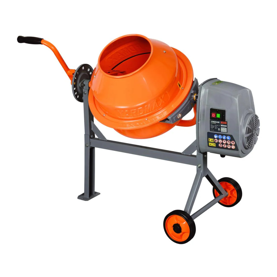
SPECIFICATIONS
| Model Number | YM0046 |
| Cubic Feet | 1.6 |
| Motor | 120V- 60Hz, 150W |
| Horsepower | .2HP |
| IP45 Washdown | Yes |
| Drum Type | Steel |
| Weight Capacity | 100 lbs |
| Number of Blades | 2 |
| Opening Diameter | 9" |
| Product Weight | 53 lbs |
SYMBOLS
The rating plate on your machine may show symbols. These represent important information about the product or instructions on its use.
 Read these instructions carefully. |  Replace damaged, missing or failed parts before using it. |
 Wear eye protection. Wear hearing protection. |  Keep hands out of the way of all moving parts. |
 Wear protective gloves. |  Do not place any part of your body or any tool, like shovel in the drum during operation. |
 Wear safety footwear. |  When operating, do not pass hands through the clearance between frame and support arm or the one between the drum and support arm. |
 Only use or operate the mixer on solid, flat, level ground that is capable to support the weight of the mixer and its load. To prevent the mixer from tipping over, only use or operate the mixer on solid, flat, level ground capable of supporting both the weight of the mixer and its contents. |  Do not start the motor if the drum is fully loaded. Do not turn mixer off while full of concrete. |
 Do not attempt to move the mixer when it is loaded and/or in operation. |  Take left over materials to an authorized collection point or follow the stipulations in the country where the mixer is used. Do not discharge into drains, soil or water. |
 Check your mixer before turning it on. Keep guards in place and in working order. |  Keep children and bystanders off and away. |
 Disconnect the main plug prior to the repair, cleaning, and maintenance of the mixer! |
SAFETY
KNOW YOUR CONCRETE MIXER
Read this manual and all labels to understand your YARDMAX concrete mixer and its limitations and potential hazards.
DRUGS, ALCOHOL, AND MEDICATION
Do not operate your concrete mixer while under the influence of drugs, alcohol, or any medication that could affect your ability to use it properly.
AVOID DANGEROUS CONDITIONS
Secure your concrete mixer on level ground. Keep your work area clean and well lighted. Cluttered areas may cause injuries. Do not use your concrete mixer in wet or damp areas or expose it to rain. Do not use it in areas where fumes from paint, solvents, or flammable liquids pose a potential hazard.
To prevent the mixer from tipping over, only use or operate the mixer on solid, fiat, level ground capable of supporting the weight of both the mixer and its load. Do not attempt to move the mixer when it is loaded and/orin operation. This mixer is intended for the production of concrete, mortar and plaster. It is not suitable for the mixing of flammable or explosive substances. Do not use it in areas where fumes from paint, solvents or flammable liquids pose a potential hazard.
INSPECT YOUR CONCRETE MIXER
Check your mixer before turning it on. Keep guards in place and in working order. Do not plug mixer with motor cover off. Check all bolts, nuts, and screws for tightness before each use, especially those securing guards and drive mechanisms. Vibration during mixing may cause these to loosen. Form a habit of checking to see that all the adjusting tools, shovels, hand trowels and other tools/equipments are removed from mixer area before turning it on. Replace damaged, missing or failed parts before using it.
Warning labels carry important information. Replace any missing or damaged warning labels.
DRESS PROPERLY
Do not wear loose clothing, gloves, or jewelry (rings, watches) that can be caught in moving parts. Wear protective, nonconductive gloves and non-skid footwear. Pull long hair back or wear a hat to prevent hair from getting caught in the machine.
PROTECT YOUR EYES
Always wear safety glasses. Concrete mixers can throw foreign objects into the eyes, causing permanent eye damage. Every day glasses do not have impact-resistant lenses and should not replace safety glasses. Z87 rated glasses are recommended.
PROTECT YOUR BODY
Always stand behind the concrete mixer and stay alert.
KEEP VISITORS AND CHILDREN AWAY
Keep unauthorised persons away from the mixer. Do not allow children to handle or climb on or in the mixer.
EXTENSION CORDS
Improper use of extension cords can cause the motor to overheat. Your extension cord should be no longer than 30 feet and a minimum of 12 gauge with a 3-prong grounded plug.
Avoid use of free and inadequately insulated connections. Connections must be made with protected material suitable for outdoor use. Make sure that any extension cord connections are dry and safe. Ensure that the extension cord is carefully laid out avoiding liquids, sharp edges and places where vehicles might run overit. Avoid allowing the extension cord to be trapped underneath the mixer. Unroll it fully or it will overheat and could catch fire.
AVOID ELECTRICAL SHOCK
Do not plug or unplug the motor while standing in or around damp or wet ground. Do not use the mixer in wet or damp areas or expose it to rain. Prevent body contact with grounded surfaces: pipes, radiators, ranges, and refrigerator enclosures. Make sure your fingers do not touch the plugs metal prongs when plugging or unplugging the mixer.
Do not touch the electric wires inside the motor cover. For any service please contact YARDMAX or an authorized service center. Make sure your fingers do not touch the plug's metal prongs when plugging or unplugging the concrete mixer.

Stay of clear of all moving parts!
DON'T OVERREACH
Keep proper footing and balance at all times when loading or unloading the mixer. Never stand on mixer. Serious injury could occur if the mixer is tipped or if the moving parts are unintentionally contacted. Do not store anything above or near the mixer where anyone might stand on the mixer to reach them.
AVOID INJURY FROM ACCIDENTS
Keep hands out of the way of all moving parts. Do not place any part of your body or any tool - such as a shovel - in the drum during operation. When operating, do not pass hands through the clearance between frame and support arm, or through the space between the drum and the support arm.
PROTECT YOUR HANDS
Keep your hands away from all moving parts. Do not place any part of your body in the drum, or under the finger guard, at any time while the motor is on.
DO NOT FORCE TOOL
Do not use the concrete mixer for any other purpose than that for which it was intended. Do not start the motor if the drum is fully loaded. Do not turn the mixer off if it still contains mixer is not to be towed.
NEVER LEAVE MACHINE UNATTENDED
Do not leave concrete mixer until it has come to a complete stop.
DISCONNECT POWER
Unplug your concrete mixer when not in use and before making adjustments, changing parts, cleaning, or servicing. Consult the technical manual before servicing.
PROTECT THE ENVIRONMENT
Take left over materials to an authorized collection, follow the stipulations in the country where the mixer is used. Do not discharge into drains, soil, or water.
MAINTAIN YOUR CONCRETE MIXER WITH CARE
Keep your concrete mixer and its parts clean.
CHILDPROOF YOUR WORKSHOP
Store your con
CONTENTS SUPPLIED

- Upper Drum
- Bottom Drum Support Arm
- Locking plate
- Motor assembly
- Tipping Bar
- Mixing Blades (1 Pair)
- Suporting leg
- Support frame
- Wheel axle bracket
- Wheels (1 pair)
- Motor support bracket
- Operator's manual
- Hardware Bag


ASSEMBLY
This concrete mixer is partially assembled at the factory. To assemble your machine, follow the below instructions.
 Assembly requires two persons (recommended).
STAND
- Slide the each wheel in each stub axle. Insert each split pin into the axle hole. Bend each of the side pins outward so they do not fall out. Attach the wheel caps.


- With the frame lying on its side, attach the support legs. Align the 2 holes on the support leg with the frame holes as shown. (See Figure 1b, Illustration 1) Screw M8x40 hex bolt and washer into the upper hole. (See Figure 1b, Illustration 1). Insert M8x60 hex bolt through the lower hole, and secure with fiat washer, lock washer, and nut. (See Figure 1b, Illustration 2).


- Turn the frame over and attach the axle bracket with wheels the same manner. (See Figure 1c Illustrations 1-2)


- Make sure all bolts and nuts are tightened.
BOTTOM DRUM

- Slide the motor support bracket on the shaft. (See Figure 2, Illustration 1)
- Carefully place the bottom drum with support arm onto the side supports of the stand as shown. (See Figure 2, Illustration 2). The motor support bracket and support seat should slide into the side support channel on each side. The larger diameter shaft should be at the leg end of the stand.
- On each side, line up the holes in the side support with those in the the motor support bracket and support seat, insert a M8x55 hex bolt from one side, then a flat washer, lock washer and nut from the other side. Tighten with a wrench. (See Figure 2, Illustration 3)
MIXING BLADES
Mount the mixing blades inside the bottom drum loosely as shown (See Figure 3, Illustration 1) Two holes are provided at the base of the drum into which a M8x20 screw may be inserted from the outside. A leather washer and a nut should be threaded on loosely on the inside. The leather washer should be placed under the blade down against the drum. (See Figure 3, Illustration 2)

 Note the arrow labels on your mixer - one on the top drum and one on the bottom. If you have difficulty correctly positioning the mixing blades, temporarily mount the upper drum on the top of the bottom drum, and rotate the top so the two arrows align.
UPPER DRUM

- Place the upper drum onto the bottom drum by aligning both the mounting holes, and the labeled arrows. (See Figure 4, Illustration 1 & 2)
- Insert a M6x 16 cross headed screw into each mounting holes in the rim. Secure each screw from below with a lock washer and nut. Make sure the tightening process is carried out progressively. (See Figure 4, Illustrution 3)
- Secure the mixing blades to the upper drum by inserting two M8x16 cross headed screws, from the outside through the holes in the drum.
- A leather washer should be positioned inside between the drum and blade. Secure the mixing blade on the inside using a nut. (See Figure 4, Illustration 4)
- Finally, ensure top and bottom mixing blade mountings are tight.
TIPPING BAR
- Slide the locking plate over the large diameter shaft (at the "leg side" of the frame) with the rim facing inwards as shown. Insert two M8x25 bolts into the mounting holes, and secure each with a nut and flat washer. (See Figure 5a)


- Insert the spring into the bar pipe, hold the spring in place with a finger, and place the bar over the larger diameter shaft so the spring stays inside the bar pipe. (See Figure 5b, Illustration 1) Press down on bar pipe until the holes in the bracket line up with the hole drilled in the shaft. (See Figure 5b, Illustration 2)
Insert a M8x55 hex bolt through the hole, place a flat washer on the bolt, and secure with nut. (See Figure 5b, Illustration 3)
Secure the nut against the bracket (do not over-tighten, as this will prevent the bracket from pivoting on the bolt).

![information]() The bar must be allowed to pivot about the bolt so that the lugs on the bracket can be engaged or disengaged from the slots in the locking plate.
The bar must be allowed to pivot about the bolt so that the lugs on the bracket can be engaged or disengaged from the slots in the locking plate.

TRANSMISSION & MOTOR
Align the pinion shaft with the bushing sleeve in the transmission and slide into place. (See Figure 6, Illustration 1) Align the bolt holes in the frame bracket with the bolt studs and the holes of lower mount bracket in the motor case and slide into position. (See Figure 6, Illustration 2) Secure the motor case to the frame bracket using four M8 lock nuts. Secure the lower mount bracket to the frame with one M8x60 bolt, two flat washers and a lock nut. (See Figure 6, Illustution 3)

KNOW YOUR MACHINE
FEATURES AND CONTROLS

OPERATION
ELECTRICAL REQUIREMENTS
Confirm that you have a US Standard, 3 pin grounded, Type B, 15AMP (NEMA 5-15) outlet.
Check that the electric circuit is grounded, adequately protected, and that it corresponds with the power, voltage, and frequency of the motor.
ELECTRICAL CONNECTION
This mixer is double insulated to Class II protection and IP44D rated. The insulation will only remain effective if the original insulating parts are used for repairs and the spaces between the original insulation are maintained.
This mixer is double insulated to Class II protection and IP44D rated. To keep this rating, it is critical that the disassembly and reassembly of the electric control enclosure is performed properly. Only a qualified electrician is allowed to repair the enclosure of electric control.
Double insulation ( ) eliminates the need for the three-pronged, grounded power cord and a grounded power supply system. Double-insulated devices can use either a two- or a three-pronged extension cord.
Do not connect either cord to the earth pin.
STAKE ON LEVEL GROUND
To secure your YARDMAX concrete mixer during operation, use two longer bolts or stakes through the holes in the front leg of the mixer stand to hold the mixer in place. (See Figure 7) Due to varying ground surfaces, these are not included. Choose the right type of bolt or stake for your surface type or call us for a recommendation.

DRUM TILTING
The spring-loaded tipping bar with locking lugs allows for tipping control of the drum (See Figure 8a), and can be locked in the following positions (see Figure 8b): Loading/Mixing - mortar, Loading/Mixing - concrete, Discharging, and Storage.


The drum is locked into the desired position by the lugs on the self-locating tipping bar, which lock into the slots on the locking plate on the mixer frame. (See Figure 8a) To tilt the drum, pull the tipping bar slightly toward you (away from the frame) to disengage the locking lugs. This allows the tipping bar to turn the drum in the desired direction.
To lock the drum in position, slightly release the tipping bar (towards the mixer frame) when rotating the drum. The lugs will slide and then lock into the nearest position on the locking plate.
LOADING
Completely unwind the extension cord. Connect it to the concrete mixer first before plugging in power supply.
Always start the motor before you start loading the drum. The mixer blades should be turning before you start adding the contents.
To avoid concrete or mortar sticking to the insides of the mixer drum, slowly pour material into the mixer steadily over the rim.
A built-in thermal protector is installed in the motor to prevent overheating, and will cool automatically as the motor cools.
For best results, always load the mixer in the following order:
- Add the required amount of gravel into the drum.
- Add the required amount of cement into the drum.
- Add the required amount of sand into the drum.
- Pour the required amount of water into the drum.
EMPTYING
Do not turn the mixer off (stop rotating arms) if you have content inside the bin. Always empty the drum completely with the mixer arms rotating.
CLEANING
Never put hands or limbs inside the drum while the mixer arms are rotating.
Thoroughly clean the mixer at the end of each days operation. Keep your mixer clean. The slightest trace of material left in the drum will harden and accumulate more each time you use it until the machine no longer will operate. Dried cement should be scraped out of the drum. Do not throw bricks into mixer drum to clean it out. Do not beat on the drum with a shovel, a hammer or other tools to break up accumulations of dried cement mix, as damage to the mixer may result. The drum may be scoured for approximately 2 minutes, using 1" gravel and water mixture. Then discharge the gravel/water mixture and hose down the drum assembly inside and out. The IP44D protection class construction of the concrete mixer enables you to hose down the drum assembly safely.
Do not pour or spray water directly over the motor cover, especially the openings in it.
Wipe off any external material on the motor cover. Do not use petrol, turpentine, lacquer or paint thinner, dry cleaning fluids or similar products. The use of chemical products or solvents may affect the properties of the cover which was made of high density polyethyiene PET.
MAINTENANCE
Ensure the extension cord is always unplugged before the motor cover is removed.
The drive belt maintains a constant, even tension provided by the spring-loaded jockey. No adjustment is needed other than an occasional touch of grease on the spindle.
The bearings are sealed for life.
The wiring diagram and parts schematic in this manual are for reference purposes only. Neither the manufacturer nor distributor makes any representation or warranty of any kind to the buyer stating that he or she is qualified to make any repairs to the product, or that he or she is qualified to replace any parts of the product. Only qualified technicians should repair the mixer. Any maintenance and repairs to any of the electric components must be performed by a qualified electrician.
Parts in a circle should only be fitted by a qualified electrician.
REPLACING THE BELT
- Remove the motor. (see Figure 9a)


- Remove the motor cover. (see Figure 9b, Illustration 1)
- Turn the idle pulley and pull out the belt. (see Figure 9b, Illustration 2)

- Assemble the new belt and reattach the cover and motor assembly.

WIRING DIAGRAM

TROUBLESHOOTING
| Problem | Cause | Remedy |
Motor stops working | Thermal protector works | Stop working for a while until motor cools |
Drum fails to rotate |
|
|
PARTS DIAGRAM

PARTS LIST
| No. | Description | QTY. | No. | Description | QTY. |
| 1 | Cross Headed Screw M8X16 | 2 | 34 | Bolt M3.5*12 | 3 |
| 2 | Waterproof Washer 8 | 4 | 35 | Gear Guard - Short | 1 |
| 3 | Lock Nut M8 | 16 | 36 | Motor Support Bracket | 1 |
| 4 | Mixing Blade | 2 | 37 | Circlip 12 | 1 |
| 5 | Cross Headed Screw M6X16 | 10 | 38 | Gear Guard - Long | 1 |
| 6 | Flat Washer 6 | 10 | 39 | Bearing 6001 | 2 |
| 7 | Lock Nut M6 | 10 | 40 | Flat Washer | 1 |
| 8 | Upper Drum | 1 | 41 | Drive Shaft | 1 |
| 9 | Rubber Gasket | 1 | 42 | Drive Pinion | 1 |
| 10 | Bottom Drum | 1 | 43 | Lock Pin 5*40 | 1 |
| 11 | Waterproof Washer 6 | 4 | 44 | Circlip 20 | 2 |
| 12 | Flat Washer 8 | 16 | 45 | Bearing 61804 | 2 |
| 13 | Bolt M8*60 | 3 | 46 | Bolt M3.5X16 | |
| 14 | Wheel Axle Bracket | 1 | 47 | Belt | 1 |
| 15 | Wheel | 2 | 48 | Idle Pulley | 1 |
| 16 | Split Pin | 2 | 49 | Bolt M6X8 | 1 |
| 17 | Wheel Plug | 2 | 50 | Drive Pulley | 1 |
| 18 | Bolt M8*55 | 3 | 51 | Motor | 1 |
| 19 | Support Frame | 1 | 52 | Fan | 1 |
| 20 | Bolt M8*40 | 2 | 53 | Circlip 15 | 1 |
| 21 | Tipping Bar | 1 | 54 | Gasket | 1 |
| 22 | Spring | 1 | 55 | Switch | 1 |
| 23 | Handle Grip | 1 | 56 | Motor Cover | 1 |
| 24 | Locking Plate | 1 | 57 | Strain Relief Nut | 1 |
| 25 | Support Seat | 1 | 58 | Electric Cord | 1 |
| 26 | Bolt M8*25 | 2 | 59 | Strain Relief Rubber | 1 |
| 27 | Circlip 32 | 2 | 60 | Strain Relief Bolt | 1 |
| 28 | Support Arm | 1 | 61 | Strain Relief Nut | 1 |
| 29 | Support Leg | 1 | 62 | Bolt M8X30 | 2 |
| 30 | Bearing Flange - Upper | 1 | 63 | Motor Mount Bracket | |
| 31 | Bearing 6204 | 2 | 64 | Bolt M8X25 | 2 |
| 32 | Bearing Flange - Lower | 1 | 65 | Gasket | 1 |
| 33 | Cross Headed Screw M8X20 | 2 | 66 | End Plate | 1 |
MODEL AND SERIAL NUMBERS For future reference, record both the model number (see Figure 1, Illustration a) and the serial number (see Figure 1, Illustration b), as well as date and place of purchase. Have this information available when ordering parts, optional accessories and when making technical or warranty inquiries.

SUPPORT
Have questions about your YARDMAX equipment? Call us at 844-YARDMAX, email us at support@yardmax.com, or contact us via your favorite social media site.
844-YARDMAX (844-927-3629) | info@yardmaxcom
Documents / ResourcesDownload manual
Here you can download full pdf version of manual, it may contain additional safety instructions, warranty information, FCC rules, etc.
Advertisement


Need help?
Do you have a question about the YM0046 and is the answer not in the manual?
Questions and answers