Pfannenberg DTS, DTI 6x01 Manual
- Operating and installation instructions (12 pages) ,
- Operating and assembly instructions manual (37 pages)
Advertisement
Hints on the manual
This handbook contains instructions for the installation and operation of
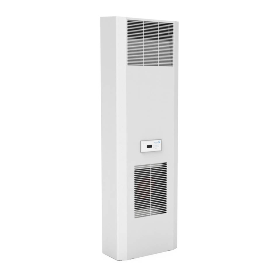
- Door and side-mounted, bolt-on Cooling Units, Series DTS 6x01,
- Door and side-mounted, built-in Cooling Units, Series DTI 6x01.
Hint
The technical specifications for each machine along with additional information on assembly, connections and operation are contained in a separate sheet.
In this manual, safety recommendations and other information are structured as follows:
 Hazard
If the measures described in the following are not strictly observed there is danger to life and health.
 Hazard
If the measures described in the following are not strictly observed there is danger to life and health due to electrical shock.

If the measures described in the following are not strictly observed material damage may be caused.
Hint
A hint contains additional information on the action or instruction described.
Handling
Transport
- Lift cooling unit only by the casing or with two jack rings (M8)
- Transport the cooling unit only in condition of usage.
- Prior to transport remove the cooling unit and pack it separately if the complete switch cabinet is to be transported.
Failure to observe these instructions will render the warranty provisions null and void.
Storage
- Never expose cooling units to temperatures exceeding +70°C during storage.
- Store cooling unit only in condition of usage.
Failure to observe these instructions will render the warranty provisions null and void.
Unpacking
- Prior to and during unpacking make a visual inspection of the cooling unit to see whether any damage has occurred during transport. Especially pay attention to loose parts, dents, scratches, visible loss of oil etc.
- Any damage must be reported immediately to the forwarding agent (follow the instructions in "Rules for Damage Claims"). Moreover, the latest edition of the "General Conditions for Supplies and Services" issued by the ZVEI (Central Association for the German Electrotechnical Industry") shall apply.
- Before disposing of packing material ensure that it does not contain any loose components.

Burr caused by production may be present on the metal edges of the unit. Always wear protective gloves when carrying out maintenance work and installation.
In case of a warranty claim exact details on the fault (photograph, if possible) and the indication of type and serial number of the cooling unit are required.
Scope of delivery and options
Scope of delivery
The Scope of delivery includes:
- Cooling unit,
- Operating manual,
- Supplement sheet,
- Enclosed package, (gasket, fastening material, electrical plug type connectors)
- Special accessories, if applicable.
Options
The following parts may be ordered separately:
- Filter adapter
- Fleece filter; (Filter adapter required)
- Textile filter; (Filter adapter required)
- Metal filter; (Filter adapter required)
- Further options on request or in accordance with the catalogue.
General Information
- Old devices can be properly disposed of by Pfannenberg. They must be sent to one of our works shipment/postage paid.
- All cooling units produced by Pfannenberg are free from
- silicone compounds,
- PCB,
- PCT,
- asbestos,
- formaldehyde,
- cadmium,
- substances impairing wetting.
- All cooling units are ROHS compliant.
- Every cooling unit is checked to ensure that it is tight according to the provisions of UVV-BGV D4 (German regulations covering accident prevention).
- Prior to delivery the electrical safety of every cooling unit is factory tested. This means that, in accordance with UVV-BGV A2, §5 (4), the operating company is released from the obligation to arrange for a test of the electrical part of the cooling unit before initial start of operation.
ID Plate and Technical Data
For installation and maintenance, note the data on the ID plate; it is to be found on the back of the cooling unit casing
The technical details applicable to the cooling unit are in the accompanying supplement sheet or on our homepage (www.pfannenberg.com).

Function
Principles of function

- Compressor
- Heat exchanger (condenser)
- Expansion valve
- Heat exchanger (evaporator)
- fan, exterior circulation
- fan, inner circulation
- Electronic control system with temperature sensor
The compressor (1) compresses the refrigerant until high pressure is achieved. During this process temperature increases. In the condenser (2) heat is dissipated to ambient air, the coolant becoming liquid. The condenser fan (5) of the condensator takes ambient air in through the condenser, then it releases the air. In the expansion valve (3) the pressure of the coolant drops. In the evaporator (4) the coolant absorbs heat from the air in the switch cabinet and evaporates. Thus, the air in the switch cabinet cools down. At the same time the air inside the switch cabinet is being dehumidified. The evaporator fan (6) sucks the air out of the switch cabinet via the evaporator, the cooled air flows back to the switch cabinet.
The cooling unit is electronically controlled. For that purpose a temperature sensor records the temperature of the air inside the switch cabinet (7).
The refrigerant is not detrimental to the ozonosphere; it is hardly combustible.
Condensate
During cooling on the evaporator the moisture removed from the air is collected as condensate. In order to avoid any damage to the switch cabinet and the cooling unit, the condensate must be discharged.
The condensate is evaporated into the surroundings with an integrated evaporator. For safety reasons, there is a drain nozzle on the evaporation unit on which the drain hose is attached.
In order to selectively collect any condensate arising, a condensate collection bottle is available as an accessory (art. no. 18314000100).
Excessive condensation can occur if, for example, the switch cabinet is not sealed or if the internal temperature of the switch cabinet is frequently below the dew point.
If there is excessive condensate during normal operation check the sealings of the switch cabinet.
We recommend that you install a door contact switch to switch off the cooling unit, when the door of the switch cabinet is opened, in order to prevent excessive condensate.
Installation
General
- The installation place for the switch cabinet must be selected such that proper ventilation of the cooling unit is ensured.
- The single units or the units and the wall must be at a distance of 200 mm at least.
- Air circulation in the switch cabinet must not be impeded by builtin parts.
- The assembly of the cooling unit can be carried out with and without a cover (external). (The unit must be disconnected from the power supply!)
- The site of installation must be protected against contamination.
If the cooling unit is mounted on a switch cabinet door, it must be confirmed that the hinges can support the additional weight or that the switch cabinet will not topple over when the door is opened.
Chips may damage the switch cabinet.
If the required cutouts are only made in the switch cabinet just before mounting of the cooling unit, make sure that swarf is not allowed to enter the device hood by using a cover sheet, for example.
Hint
To facilitate installation with heavy units, M8 lifting eyes can be screwed into the upper fixing on the equipment housing. Simple „one man installation" is thereby possible.
Installation of side-mounted bolt-on cooling unit DTS
The mounting surface of the switch cabinet is to be provided with cutout(s) and holes for air ventilation openings and for securing the unit according to the accompanying sheet.
The drawing on the accompanying sheet also shows the location of the electrical connections and ventilation openings.
- Make cutout(s) and drillings for the cooling unit, if not already provided in the switch cabinet (see drawing on accompanying sheet).
Remove burrs from the cut edges - Position the profile seal around the rim of the cutout(s). Position the seal so that the impact ends are facing downwards.
![]()
- Screw the two threaded studs included in the component pack into the upper fixing point of the cooling unit. Suspend the unit from outside onto the switch cabinet using the threaded studs.
- Use the screws, nuts and washers included in the component pack to secure the cooling unit on the inner side of the switch cabinet. Tighten up fixings so that the seal is compressed to a thickness of 2 mm.
- The condensate emergency drain is located in the base of the device.
- If the cooling unit is mounted without the device hood, plug the earth cable and the connecting cable to the display unit on the hood and mount this on the cooling unit.
- Clamp the cable as shown in the connection diagram (see back of unit) to the plug (component pack) and connect to the unit.
- conductor size: 0,5 – 2,5mm² or AWG20 - AWG14 (In the selection of cable size, the relevant regulations must be observed!)
- Connect the unit to the electrical supply (see Section "Power Connection").

Installation of built-in cooling unit DTI
The mounting surface of the switch cabinet is to be provided with a rectangular cutout as shown on the accompanying supplement sheet.
The drawing on the supplement sheet shows the location of the ventilation openings after mounting the unit.
- Make cutout for the cooling unit, if not already provided in the switch cabinet (see drawing on accompanying supplement sheet). Remove burrs from the cut edges
- From the outside, insert the cooling unit (Pos. 1) into the cutout and push through until the unit seal engages with the switch cabinet (Pos. 2). Close the snap-fastener (Pos.4) with an audible click from the unit on upper side and secure the unit against falling out.

- Cooling Unit DTI
- Switch cabinet wall or door
- Securing spring
- Snap
- On the inside of the switch cabinet, make sure that the securing springs (Pos. 3) supplied in the component pack rest in their locations. To do this, compress the springs by hand so that the securing bracket can be secured in the housing cutout (Pos. A).
In switch cabinets with reinforcing frames, insert the securing springs in the rear of the housing cutouts (Pos. B). - The condensate emergency drain is located in the base of the device.
- If the cooling unit is mounted without the device hood, plug the earth cable and the connecting cable to the display unit on the hood and mount this on the cooling unit.
- Clamp cables in accordance with the connection diagram (see rear of unit) to the plug-in connectors (enclosed package) and connect to the unit.
- lead cross-section: 0.5 – 2.5 mm², and/or AWG20 – AWG14 (for the selection of the cable cross-section the relevant provisions are to be taken into account).
- Connect the cooling unit to the power source (see Section "Power Connection").

Power connection
- The cooling unit must be connected to the mains by means of a disconnecting device with a contact gap of at least 3 mm when switched off.
- No temperature control must be series-connected to the cooling unit feed.
The fuse as indicated on the ID plate must be series-connected as line protection. - Power connection and repairs, if applicable, may only be carried out by authorized trained electricians.
Power supply connection
Both mains voltage and frequency must correspond to the nominal values indicated on the ID plate of the cooling unit.

- The installation of the power cable is not subject to any special requirements
Attention: The cooling unit may be damaged if the voltage is too high.
Refers to cooling units for nominal voltages 400 V/460V.
As an option, some units, different to the standard (400 V/460 V), may be connected to a different mains voltage (For voltage range see enclosed sheet).The feed cables on the transformer primary must be unclamped for this.
Attention! The cooling unit may be damaged due to incorrect direction of rotation.
Before switching on the unit, check the phase sequence of the three-phase supply in order to prevent damage to the compressor. Direction of rotation must be to the right (clockwise). The correct pin assignment is indicated by an illuminated LED in the connection area. With a flashing or dark LED the pin assignment must be checked.
Door contact
The door contact is supplied form the cooling unit with an extra-low voltage (<20V, 20 mA).
- In order to avoid any disruptive influences, it is recommended that a sheathed cable with twisted pair leads be used. The screen can be secured on one side to the PE connection point provided on the cooling unit.
- If the use of sheathed cables is not possible, during installation of the cables it must be ensured that they are not routed in the immediate vicinity of potential interference sources (e.g. supply lines, components with relatively high electromagnetic emission).

No external voltage may be applied
If no door-contact switch is used, the connecting contacts are to be bridged.
Centralised fault indication
For connection of the fault signal line there are 2 connection contacts and/or connecting lines available (see circuit diagram on the Technical Supplementary Sheet)
The installation of the fault signal line is not subject to any special requirements.
The contact may be loaded with max. 230 V, 1A.
Multimaster
(Optional, only for units with Multi-Controller)
To connect the multimaster cables there are in each case 2 connecting contacts (input and output-end) available (see connecting diagram on the rear of the housing).
The contacts are supplied with low voltage (< 20 V, 20 mA) from the cooling unit.
No external voltage may be applied
- In order to avoid any disruptive influences, it is recommended that a sheathed cable with twisted pair leads be used. The sheath can be connected at both ends to the PE terminal provided on the cooling unit for the purpose.
- If the use of sheathed cables is not possible, during installation of the cables it must be ensured that they are not routed in the immediate vicinity of potential interference sources (e.g. supply lines, components with relatively high electromagnetic emission).
- A maximum of 20 units may be controlled over the bus.

Block diagram of the Multimaster wiring
For more information see also Multimaster – bus chapter
Operating Conditions
- Voltage must be within ± 10% of the value indicated. Frequency must be within ± 3 Hz of the value indicated.
- Ambient temperature must be below 55°C (for options see supplement).
- Use the unit such that the cooling capacity suits the actual demand.
- Use refrigerant as indicated only.
- Use genuine spare parts only.
Putting into operation and function
General remarks
The cooling unit is provided with an electronic control system. The drawn-in switch cabinet internal air temperature is measured by a temperature sensor. By means of a DIP switch on the control board, different switch cabinet temperatures as well as upper limit temperatures can be selected (see accompanying supplement sheet). With devices with Multi-Controller the adjustment takes place by means of a USB cable and the configuration software ECoolPLANT, including the USB driver software. Exceeding the limit temperature generates an alarm. For units with Multi-Controller, the lower temperature limit can also be monitored.
Ambient conditions and temperature in the switch cabinet must be in accordance with the values indicated in the supplement.
Too little heat transfer at the heat exchanger in the external circuit (condenser)..
The cooling unit may only be operated with cover, otherwise heat dissipation at the condenser is not sufficient, and the cooling unit may be damaged.
Immediately after the switch-on of the service voltage, the unit goes into the start-up/test mode. After that the evaporator fan continues to run. Compressor and condenser fans run on as required (the temperature of the switching threshold (Tset) has been reached, or are switched off (temperature lower than switching threshold (Tset)).
- Free discharge of any condensate produced must be provided to ensure trouble-free operation.
Indicator elements
The cooling unit with standard controller has an operational display in the form of an LED on the external hood of the unit. If the light of this indicator remains on when the supply voltage is applied it shows that the unit is in the normal operating mode. If a fault occurs or if the unit is in the start-up or test mode, this indicator lights up in various flashing sequences which make it easier to diagnose fault in the unit (see Sections "Unit characteristics" and "What to do if")
The cooling unit with multicontroller has a temperature display.
Test mode / start-up
The test mode is basically activated after renewed connection of the supply voltage and is independent of the instantaneous ambient conditions when the door contact is closed.
First of all the unit runs through a start-up mode lasting 30 seconds which is followed by a test mode lasting 30 seconds.
Unit characteristics
| Modus | Time curve | Characteristics |
| Start-up mode | t = 0s - < 30s t = 30s t = 32s | No function Internal fan start up External fan and compressor start up Flashing sequence of the status indicator: "off-dark-light-dark-off". Fault signal contact is closed. |
| Test mode | t >34s – 64s. | Compressor and fans remains in operation during the period. Flashing sequence of the status indicator: "off-dark-light-dark-off". Fault signal contact is open. Should a fault arise during the test mode, the unit goes into the fault mode and the status indicator lights up according to the fault state (see chapter on Fault diagnosis) |
The start-up mode is always additionally activated when the door limit switch is closed (see Section "Door contact")
Door contact
To avoid an increased production of condensate and for safety reasons a door limit switch should be connected to the terminals provided (see circuit diagram in the interior panel behind the internal fan or in the accompanying supplement sheet)
By the opening of the switch cabinet door and thus the opening of the switch all of the motors of the cooling unit are immediately switched off. After closing of the door the start-up mode (see Section "Unit characteristics") is run through which ensures a restart-up of the cooling unit with a time lag.
Centralised fault indication
The signalling of a fault in the cooling unit is effected by the breaking of a potential-free contact (see Section "What to do if"). In this way a cable breakage in the fault signalling line is also signalled.
Energy mode
(Optional, only for units with Multi-Controller)
- If the cooling unit is not in active cooling operation for 15 minutes, it switches to energy mode. This is shown in "Application error" rhythm (Consequence 1) by a flashing LED and with "En" in the display.
- Energy mode is interrupted by a cooling command (switch cabinet interior temperature above the target temperature, which means the cooling unit is in active cooling mode). Cooling mode is maintained until the target temperature (less hysteresis) is reached. After an additional 15 minutes the device switches back to energy mode.
- If device errors arise in energy mode, the cooling unit will behave in accordance with the fault diagnosis.
- If the target temperature (less hysteresis) is undercut at the external temperature sensor during energy mode, the internal fan is switched off. If the target temperature (plus hysteresis) is exceeded at the external temperature sensor, the internal fan is switched on.
- As long as no error occurs in the unit, the fault message output of the device is closed in energy mode (no error).
Multimaster – bus
(Optional, only for units with Multi-Controller)
In the multimaster configuration, cooling operation is initiated by the cooling unit which reaches the operating threshold (Tsetp. + 2K) first. All of the cooling units connected to the multi-master bus switch to cooling operation. The cooling mode is terminated by the unit which is the last to go below the operating threshold (Tsetp. - 2K).
For all cooling units which are operated in combination through a Multi-Master control, the execution of the energy function is switched off by the cooling command of one of the units from the combination.
After the last cooling command, the cooling units return to energy mode after the lapse of the set delay time
Setting possibilities
By means of a DIP switch (standard controller) or using the USBinterface (Multi-Controller), various switch cabinet temperatures as well as limit temperatures can be selected.
The location of the DIP switch on the control board is shown in the circuit diagram.
The coding options are represented on the circuit diagram (Standard-Controller). The circuit diagram is adhered to the interior panel behind the internal fan and shown in the accompanying supplement sheet.
Starting with a particular set-temperature in the switch cabinet, an upper limit temperature can be selected which, if exceeded, will generate an alarm. On units with Multi-Controller, the lower temperature limit can also be monitored. See accompanying supplement sheet for factory settings.
Hint:
The ECoolPLANT service kit (article no.: 18310000002) can be used in combination with a PC for optimal maintenance, diagnosis and unit status monitoring of cooling units with multi-controllers.
The ECoolPLANT service kit is a Pfannenberg software package that, with the aid of the provided USB-cable (type A/B), allows the following information to be visualised:
- unit data/status
- parameter settings
- temperature recording
- error memory information
Please find more detailed information about the ECoolPLANT software and the possibility to download the software free of charge on the Internet at www.pfannenberg.com;
Changes to the parameters of the unit set in the works may be made only by authorised persons!
Isolate the cooling unit from the mains before changing the DIP-switch settings. Otherwise the modified settings won't be accepted.
Cleaning and Maintenance
Hazard!
Isolate the cooling unit from the mains before carrying out any cleaning or maintenance operations.
Cleaning
The cleaning intervals depend upon the relevant operating conditions. In particular observe the following instructions.
- Clean the heat exchanger regularly.
- Clean the heat exchanger using a soft brush or pressurized air.
- We recommend that the condensate run-off opening be checked regularly.
Proceed as follows:
- Disconnect the cooling unit from the power supply.
- Removing the unit hood:
Remove the screws (A).
Tilt the hood approx. 20°.
Remove the earthing cable and cable of the display unit on the inside of the hood.
Then raise the hood approx. 15mm and pull it out of the slots in the base plate (B).
![]()
- Clean heat exchangers

Protect the electric components against leakage.
Damage to louvres.
Do not use any pointed or sharp-edged objects. The ribs should not be compressed or damaged during the cleaning process.
Damage to electric connections on the covering hood
If the covering hood is removed, the electric plug-in connections on the inside must be removed by hand. During fitting do not forget to plug-in!!
- If the cooling units are provided with a front filter clean the filter mat regularly. The cleaning intervals or the intervals for replacement of the filter mat mainly depend upon ambient conditions (air pollution).
- You can rinse the filter mat using water heated to 40°C and commercially available mild detergent. It is possible to remove any dry dirt by knocking the mat slightly, vacuum cleaning it or blowing it out.
Damage to the filter mat.
Do not wring the filter mat. Avoid too solid a water jet.
- If the filter mat is oily or greasy, replace.
Maintenance
The cooling circuit, as a maintenance-free, hermetically sealed closed system, is filled at the factory with the necessary coolant, checked for leakages and is subjected to a functional check run. The cooling unit is largely maintenance-free. The components around the external air circuit require maintenance and cleaning depending upon the ambient conditions (see Section "Cleaning and Maintenance").
After each service, the full performance capacity of the condensate run-off should be checked.
Stopping
If the cooling unit is not in use for a longer period, disconnect it. Ensure that unauthorised persons cannot start the cooling unit.
When the cooling unit is no longer needed, it must be disposed of by authorized specialist personnel in accordance with all applicable environmental protection regulations. (see also Section "General Information")
It is essential that the refrigerant in the cooling system is properly removed by suction. Refrigerant emissions must be prevented.
What to do if
... in spite of your care and attention a fault occurs?
Check the following points first. If the fault is not then cleared, call an authorized specialist.
General errors
- No message via the service indicator
| Fault | Possible cause(s) | Remedy |
| Unit fails to cool, fan in an internal airflow circuit is running | Temperature setting too high. | Check temperature setting. |
Unit fails to cool sufficiently | Threshold values for usage exceeded. | Check ambient temperature and internal load. |
| Lack of coolant. | Call authorized specialist, check unit for leaks. | |
| Heat exchanger contaminated. | Clean heat exchanger. | |
| Fan in internal airflow circuit faulty. Fan in external airflow circuit faulty. | Call authorized specialist, replace fan. | |
| Air not circulating properly inside the switch cabinet. | Check assemblies and air circulation inside switch cabinet. Air intake and exhaust into/from cooling unit into switch cabinet must be unimpeded. | |
Unit only cools irregularly | Coding switch incorrectly set or defective. | Set higher temperature at thermostat. |
Condensate accumulates in switch cabinet | Blow-out temperature too low. | Close switch cabinet door. |
| Switch cabinet not sufficiently sealed. | Remedy leakage at switch cabinet. | |
Condensate fails to drain | Condensate drainage clogged. | Clean condensate drainage. Condensate drainage hose must be inclined downward without showing a bend. |
Condensate runs out of the unit | The condensate evaporator is defective or too much condensate accumulates. | Replace the fuses for the condensate evaporator. |
| Switch cabinet not sufficiently sealed. | Remedy leakage at switch cabinet. |
Fault diagnosis
- Message via the service indicator
If a fault occurs in the cooling unit, the status indicator goes over to flashing mode which in conjunction with the unit characteristics is to make initial fault diagnosis easier.
Flashing sequences in the fault mode can be:
| Status indicator, flashing sequence 1: (User error) |  | (5s, 1s, 1s, 1s) with periodic repetition |
| Status indicator, flashing sequence 2: (Unit fault) |  | (1s, 1s) with periodic repetition |
| Status indicator, flashing sequence 3: (Test/start-up mode) |  | (1s, 1s, 1s, 1s) with periodic repetition |
Pfannenberg units with Multi-Controller
When using a unit with Multi-Controller, the fault indication is given in the form of an error code on the temperature display. To classify the error code, refer to the „Operating Instructions Temperature display unit" provided with the documentation for the unit.
Hint:
The legibility of the display may be limited due to electromagnetic disturbances.
Pfannenberg units with Standard-Controller
The following table describes the technical cause as well as the fault remedy as a function of the unit characteristics.
| Pos | Unit characteristics | Technical causes | Fault remedy | |
| 1 | Compressor: | OFF | There is no supply of voltage to the unit. | Check back-up fuse and/or connect supply voltage |
| Internal fan: | OFF | |||
| External fan: | OFF | |||
| Status LED: | OFF | |||
| Fault signal contact: | open | |||
| 2 | Compressor: | ON | The test mode of the unit is active. This mode is left automatically at the latest after 60 s. | The unit switches to test mode once after each new connection to the power supply. No remedy of fault necessary. |
| Internal fan: | ON | |||
| External fan: | ON | |||
| Status LED: | flashing (seq. 3) | |||
| Fault signal contact: | open | |||
| 3 | Compressor: | OFF | The input for the door limit switch is open e.g. as a result of a switch cabinet door not closed or a bridge not set. | Insert link, close door contact switch or, with an engaged door contact switch, close the door |
| Internal fan: | OFF | |||
| External fan: | OFF | |||
| Status LED: | flashing (seq. 1) | |||
| Fault signal contact: | closed | |||
| 4 | Compressor: | OFF | High pressure pressostat or motor protection switch has responded (overheating) or Wrong connection assignment. Compressor switches on again automatically after the fault has been remedied (cooling) with a delay of 30 s. | Clean or replace filter or clean heat exchanger in the external circulation. Possibly check the power dissipation in the switch cabinet to the installed cooling capacity of the air conditioner. Check the connection assignment, see incorrect phase sequence chapter |
| Internal fan: | ON | |||
| External fan: | OFF | |||
| Status LED: | flashing (seq. 2) | |||
| Fault signal contact: | open | |||
| 5 | Compressor: | OFF | Unit adjustment by means of the coding switch on the control electronics is not plausible. The unit setting must be changed. | Observe the operating instructions and note the coding key of the coding switch. |
| Internal fan: | OFF | |||
| External fan: | OFF | |||
| Status LED: | flashing (seq. 1) | |||
| Fault signal contact: | open | |||
| 6 | Compressor: | ON | The upper temperature limit (T L2) of the switch cabinet has been exceeded. | Clean or replace filter or clean heat exchanger in the external circulation. Possibly check the power dissipation in the switch cabinet to the installed cooling capacity of the air conditioner. |
| Internal fan: | ON | |||
| External fan: | ON | |||
| Status LED: | flashing (seq. 1) | |||
| Fault signal contact: | open | |||
| 7 | Compressor: | OFF | The lower temperature limit of the switch cabinet has been exceeded or the water level in the condensate collection pan is too high (only with optional level monitoring). | Additionally install a heater or a fan-forced heater if necessary. Check drain for blockage or fouling. Check for correct installation of the run-off tube. Note that particularly much condensate is produced if the switch cabinet is poorly sealed or the doors are constantly open. |
| Internal fan: | ON | |||
| External fan: | OFF | |||
| Status LED: | flashing (seq. 1) | |||
| Fault signal contact: | open | |||
| 8 | Compressor: | ON | The temperature sensor TS1 is defective or has not been detected. | Replace the contact sensor TS1 or replace the complete electronic control with a fixed- wired temperature sensor. Get in touch with the service department. |
| Internal fan: | ON | |||
| External fan: | ON | |||
| Status LED: | flashing (seq. 2) | |||
| Fault signal contact: | open | |||
| 9 | Compressor: | normal control characteristics | In the switch cabinet, if a short circuit in the air circuit* occurs, no effective cooling of the switch cabinet is possible. Air-conditioning is requested within short cycle times. | Relocate the power components in the switch cabinet or relocate the cooling unit. Select a top mounting cooling unit or side-mounting cooling unit as an alternative depending on the space situation. |
| Internal fan: | ON | |||
| External fan: | normal control characteristics | |||
| Status LED: | flashing (seq. 1) | |||
| Fault signal contact: | open | |||
* Air short-circuit: An air short-circuit develops, if cool air at the air outlet of the cooling unit is led by means of power components built directly in front of it in an unfavourable way, not into the switch cabinet, but directly to the air inlet of the cooling unit. The consequence is overheating of the power components due to the lack of cooling.
Fault not rectified?
If the fault is not rectified now, please call authorised technical personnel. (technical.support@pfannenberg.com)
Safety
Cooling units produced by Pfannenberg are designed for dissipating heat from switch cabinets (IP 54). During each cooling process condensate can be produced. The cooling unit is only suitable for stationary operation.
The cooling unit may only be used under the ambient conditions specified on the accompanying supplement sheet.
The cooling unit is to a large measure maintenance-free (see Section "Cleaning and Maintenance").
Every other use is considered as non-authorized use making any warranty null and void.
The electrical equipment must be regularly checked. Any faults such as loose connections or scorched cables must be removed immediately.
Work on the cooling system and on electrical components may only be carried out by authorized specialist personnel.
Compliance with applicable safety and environmental regulations is mandatory.

Isolate the cooling unit from the mains before carrying out any cleaning or maintenance operations. Only original spare parts may be used. Please find spare parts in the accompanying supplement sheet or at www.pfannenbergspareparts.de.
Documents / Resources
References
Download manual
Here you can download full pdf version of manual, it may contain additional safety instructions, warranty information, FCC rules, etc.
Advertisement


Need help?
Do you have a question about the DTS and is the answer not in the manual?
Questions and answers