Table of Contents
Advertisement
Quick Links
Advertisement
Table of Contents

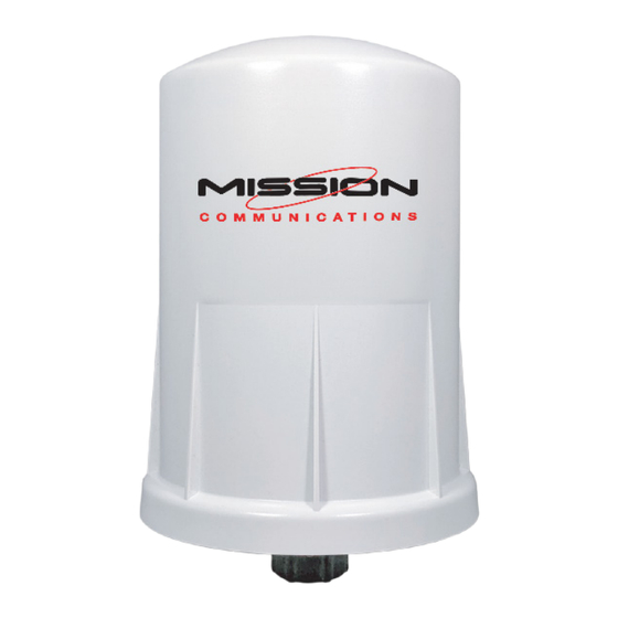
Summary of Contents for Mission Communications MyDro 54
- Page 1 MyDro 50 Node (M54) Installation Manual...
-
Page 2: Warnings And Notices
Warnings and Notices The MyDro 54 is rated Class 1 Division 2 non-incendive when powered by its internal battery pack. • WARNING: EXPLOSION HAZARD. DO NOT REMOVE OR REPLACE COMPONENTS UNLESS POWER HAS BEEN DISCONNECTED OR THE AREA IS FREE OF IGNITABLE CONCENTRATIONS. AVERTISSEMENT : RISQUE D’EXPLOSION . -
Page 3: Table Of Contents
Connections and Components ................7 Status LED ...................... 7 Error LED ......................7 Check-in Button ....................7 MyDro 54 Internal Components ..............7 Sensor Connections .................... 8 Analog Input ....................8 4–20mA Wiring Diagram ................8 0–5V Wiring Diagram ..................9 Digital Inputs .................... - Page 4 The MyDro 54 is a self–contained device that provides sensor readings over an LTE–M1 cellular network. • Powers attached analog (4–20mA / 0–5V) sensor and cellular modem with internal battery. • Dual digital inputs report state, total counts, and input frequency.
-
Page 5: Specifications
7.1in tall × 4.6in diameter, 1lb. Power Source Internal lithium battery pack. Temperature Rating -40°C to +85°C MyDro 54 SIM Slot 4FF Nano SIM card MyDro 54 Local ConfigPort Standard micro-USB connector. MyDro 54 Analog Input Three analog inputs (one built in and two on the expansion card) including 3Vdc/18Vdc, (selectable) to attached 4–20mA /... -
Page 6: Side View
Side view Bottom view... -
Page 7: Connections And Components
Check-in Button If this button is pressed the MyDro 54 will blink the green Status LED or the red Error LED 3 times to indicate the status of the last transmission to the server. If the check-in button is pressed and held for more than 1 second, the MyDro 54 will take readings from the attached sensors and send the readings to the server. -
Page 8: Sensor Connections
Sensor Connections Analog Input Screw Terminal Connections The analog input provides 13V or 18V to the attached sensor. The analog input can operate in either current (4–20mA), or voltage (0–5V). The input mode must be set by the mA or V Switch. Slide the switch up to Volts for a voltage input, or down to mA for a current input. -
Page 9: 0-5V Wiring Diagram
Sensor Setup in Active Loop 0–5V Wiring Diagram Digital Inputs The built–in digital inputs (2 total) can be dry contact or voltage (must be push- pull, 30Vdc max). Be sure to connect the ground bus from the module to either the ground of the voltage pulse device or the dry contact. -
Page 10: Relay Output
The MyDro 50 has a single latching SPDT relay which may be controlled remotely from the server or by using the MyDro 54 internal relay control logic. The relay will connect the COM terminal to NC when de-energized and the COM will be connected to the NO terminal when energized. -
Page 11: Power Options
Simply plug the battery pack into the PCB battery connector to power the MyDro 54 on. Internal Lithium Battery Replacement Battery packs can be changed with the MyDro 54 in place. 1. Unscrew the cover from the base. 2. Unplug the battery from the PCB by depressing the locking clip on the connector. -
Page 12: Test The Installation
Test the Installation Test that alarm notifications are received so they can be acknowledged by the customer or end-user once the unit is put into production. This includes phone numbers, SMS text messages, and email addresses. Additionally, the customer or end-user should test all alarms every six months to ensure all electrical components and alarm parameters are still functioning as desired and that alarms are being received and acknowledged by recipients. -
Page 13: Site Commissioning
Site Commissioning Confirm Paperwork and Credentials Ensure that: • Setup forms have been submitted to setupforms@123mc.com. • Credentials have been received by the customer and they have proper login access and connectivity to the device. If it is a new customer they should have received a welcome email to establish access to 123SCADA Web portal. -
Page 14: Installation Notes
Installation Notes _______________________________________ _______________________________________ _______________________________________ _______________________________________ _______________________________________ _______________________________________ _______________________________________ _______________________________________ _______________________________________ _______________________________________ _______________________________________ _______________________________________ _______________________________________ _______________________________________ _______________________________________ _______________________________________ _______________________________________... - Page 15 Installation Notes _______________________________________ _______________________________________ _______________________________________ _______________________________________ _______________________________________ _______________________________________ _______________________________________ _______________________________________ _______________________________________ _______________________________________ _______________________________________ _______________________________________ _______________________________________ _______________________________________ _______________________________________ _______________________________________ _______________________________________...
-
Page 16: Support
Support Webinar Mission hosts weekly webinars from 2–3 P.M. Eastern every Wednesday, except for weeks of national holidays and national trade shows. Staff members discuss the system hardware and software with live Q&A. Video Demonstrations A variety of videos are provided to cover topics relating to the MyDro 50 and the Mission system.

Need help?
Do you have a question about the MyDro 54 and is the answer not in the manual?
Questions and answers