
Related Manuals for Motorola e1070


Summary of Contents for Motorola e1070
- Page 1 Level 1 and 2 Service Manual 6809497A14-O e1070 Digital Wireless Telephone UMTS 2100, GSM 900/1800/1900 GPRS...
-
Page 3: Table Of Contents
1 and 2 E1070 6809497A14-O Level 1 and 2 Service Manual Contents Contents Introduction ................5 Product Identification . - Page 4 Contents E1070 November 10, 2005 6809497A14-O...
-
Page 5: Introduction
Available on a contract basis, Motorola Inc. offers comprehensive maintenance and installation programs that allow customers to meet requirements for reliable, continuous communications. To learn more about the wide range of Motorola service programs, contact your local Motorola products representative or the nearest Customer Service Manager. Product Identification Motorola products are identified by the model number on a label usually located under the battery. -
Page 6: Computer Program Copyrights
The Motorola products described in this manual may include Motorola computer programs stored in semiconductor memories or other media that are copyrighted with all rights reserved worldwide to Motorola. Laws in the United States and other countries preserve for Motorola, Inc. certain exclusive rights to the copyrighted... -
Page 7: Warranty Service Policy
Customer’s original units will be repaired but not refurbished as standard. Appointed Motorola Service Hubs will perform warranty and non-warranty field service for level 2 (assemblies) and level 3 (limited PCB component). Motorola High Tech Centers will perform level-4 (full component) repairs. -
Page 8: Parts Replacement
When ordering replacement parts or equipment, include the Motorola part number and description used in this service manual. When the Motorola part number of a component is not known, use the product model number or other related major assembly along with a description of the related major assembly and of the component in question. -
Page 9: Specifications
Level 1 and 2 Service Manual Introduction Specifications Table 1. Specifications Function Specification Frequency Range EGSM TX: 880 - 915 MHz Frequency (MHz) = 890 + (0.2 × n) where: 0 ≤ n ≤ 124 Frequency (MHz) = 890 + (0.2 × (n – 1024)) where: 955 ≤ n ≤ 1023 RX: 925 –... - Page 10 Introduction E1070 GSM System Functions Specification Speech Coding Type Regular Pulse excitation / linear predictive coding with long term prediction (RPE LPC with LTP) Bit Rate 13.0 kbps RF Power Output 32 dBm nominal GSM, 28.5 dBm nominal DCS / PCS Spurious Emissions -36 dBm from 0.1 to 1 GHz, -30 dBm from 1 to 4 GHz...
-
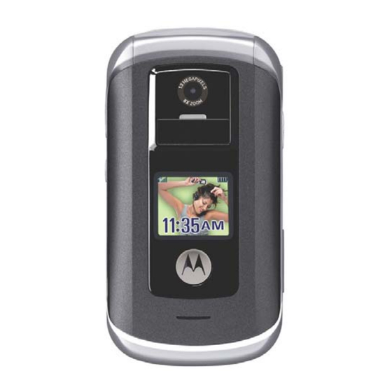
Page 11: Product Overview
Cellular System (DCS), the GSM 850 MHz, and PCS 1900 MHz bands, in addition to the UMTS WCDMA 2100 MHz band. E1070 telephones have a clam form factor. They feature an externally viewable 96 x 80 65K color CSTN CLI display for caller identification with date/time, and an internal 2 inch, 320 x 240 260K TFT color display located in the flip. - Page 12 Product Overview E1070 Video • MPEG4 Video clip playback • H.263 • RV9 Display • Main display 320 x 240 pixel 262k TFT • CLI display 96 x 80 65k CSTN Memory • 32 MB internal RAM • 64 MB internal ROM •...
-
Page 13: Simplified Text Entry
Level 1 and 2 Service Manual Product Overview Simplified Text Entry There are three different ways to enter text using the phone keypad: • iTAP predictive text entry. Press a key to enter a character, and a dynamic dictionary uses this to build and display a set of word or name options. The iTAP feature may not be available on the phone in all languages. -
Page 14: General Operation
General Operation Controls, Indicators, and Input / Output (I/O) Connections The E1070 telephone’s controls are located on the sides of the phone and on the keypad. Indicators, in the form of icons, are displayed on the LCD (see Figure 2). -
Page 15: Alert Settings
Whether a phone displays all indicators depends on the programming and services to which the user subscribes. Alert Settings E1070 telephones include up to 32 preset ring tones and vibrations that can be applied to all alert events at the same time. ➧... -
Page 16: Operation
General Operation E1070 If the battery is removed while receiving a message, the message will be lost. Operation For detailed operating instructions, refer to the appropriate user’s guide listed in “Related Publications”. November 10, 2005 6809497A14-O... -
Page 17: Tools And Test Equipment
GSM / DCS Test SIM Used to enable manual test mode. 1. To order in North America, contact Motorola Aftermarket and Accessories Division (AAD) at (800) 422-4210 or FAX (800) 622-6210; Internationally, AAD can be reached by calling (847) 538-8023 or faxing (847) 576-3023. -
Page 18: Disassembly
Disassembly E1070 Disassembly This section provides instructions for the disassembly of E1070 telephones. Tools and equipment used for the phone are listed in Table 1, preceding. Many of the integrated devices used in these phones are vulnerable to damage from ESD. - Page 19 Level 1 and 2 Service Manual Disassembly Lift the top end of the battery first and then lift the battery out the phone. (see Figure 2). Battery 051329o Figure 2. Removing the Battery There is a danger of explosion if the Lithium Ion battery is replaced incorrectly. Replace only with the same type of battery or equivalent as recommended by the battery manufacturer.
-
Page 20: Removing And Replacing The Subscriber Identity Module (Sim)
Disassembly E1070 Removing and Replacing the Subscriber Identity Module (SIM) Remove the battery door and battery as described in the procedures. Slide the SIM latch away from the SIM as shown in Figure 3. Carefully lift the SIM out of the phone. -
Page 21: Removing And Replacing The Rear Housing
Level 1 and 2 Service Manual Disassembly Removing and Replacing the Rear Housing This product contains static-sensitive devices. Use anti-static handling procedures to prevent electrostatic discharge (ESD) and component damage. Remove the battery cover, battery, SIM as described in the procedures. Using a Torx driver with a T-6 bit, remove the 6 housing screws along the sides of the phone (see Figure 4). -
Page 22: Removing And Replacing The Transceiver Board Assembly
Disassembly E1070 Carefully lift the rear housing away from the phone. Rear Housing 051339o Figure 5. Removing the Rear Housing Lower the rear housing onto the phone. Ensure the screw holes are aligned to the transceiver PCB assembly. Insert the 6 housing screws and tighten to a torque setting of 1.5 inch pounds or 16 N/cm (Newton/centimeters). - Page 23 Level 1 and 2 Service Manual Disassembly Carefully work the flat end of the disassembly tool under the flex connector and unseat the connector from its socket the transceiver board (see Figure 6). Disassembly tool Flex connector Transceiver PCB Assembly 051338o Figure 6.
-
Page 24: Removing And Replacing The Keypad
Disassembly E1070 Removing and Replacing the Keypad Remove the battery cover, battery, SIM, antenna, rear housing and transceiver PC board assembly as described in the procedures. Use the plastic tweezers to lift the keypad assembly from the transceiver PC board assembly. -
Page 25: Removing And Replacing The Antenna Assembly
Level 1 and 2 Service Manual Disassembly Removing and Replacing the Antenna Assembly Remove the battery cover, battery, SIM, antenna, rear housing and transceiver PC board assembly as described in the procedures. Turn the transceiver PC board/Switchdome/Keypad assembly over to locate the antenna assembly clips on the bottom of the transceiver PC board assembly. -
Page 26: Removing And Replacing The Switchdome Pc Board
Disassembly E1070 Removing and Replacing the Switchdome PC Board Remove the battery cover, battery, SIM, rear housing, and transceiver PC board as described in the procedures.. The flexible printed cable (FPC) (flex) is easily damaged. Exercise extreme care when handling. -
Page 27: Removing And Replacing The Flip Assembly
Level 1 and 2 Service Manual Disassembly Removing and Replacing the Flip Assembly Remove the battery cover, battery, SIM, antenna, rear housing, transceiver board assembly, and keypad assembly as described in the procedures. Avoid stressing the plastic in any way to avoid damage to either the plastic or internal components. -
Page 28: Removing And Replacing The Flip Cover
Disassembly E1070 051425o Figure 11. Removing the Flip Assembly Lift the housing assembly away from the flip assembly. Be careful not to damage the display flex cable. To replace, carefully thread the display flex connector through the slot on the keypad housing assembly. - Page 29 Level 1 and 2 Service Manual Disassembly Insert the tip of a thin bladed knife under the display lens and pry it upward. Knife blade Display lens Flip Assembly 051811o Figure 12. Removing the Display Lens Slide the pointed edge under the edge of the display lens to separate it from the flip assembly and remove it from the flip assembly.
- Page 30 Disassembly E1070 Use the T-5 driver to remove the 4 flip assembly screws at the corners of the flip assembly. Set the screws aside for re-use unless they are damaged. Flip screw Flip screw Flip Assembly Flip screw Flip screw 051427o Figure 13.
- Page 31 Level 1 and 2 Service Manual Disassembly Insert the disassembly tool into the openings on the flip housing to release the 2 latches on each side of the flip assembly. (see Figure 17). Flip Housing Catch Flip Assembly Flip Housing Catch Flip Housing Catch 0051428o...
-
Page 32: Removing And Replacing The Flip Display Pc Board Assembly
Disassembly E1070 Removing and Replacing the Flip Display PC Board Assembly Remove the battery cover, battery, SIM, antenna, rear housing, transceiver board assembly, keypad assembly, flip assembly, and flip cover as described in the procedures. The flexible printed cable (FPC) (flex) is easily damaged. Exercise extreme care when handling. - Page 33 Level 1 and 2 Service Manual Disassembly Use the pointed end of the disassembly tool to lift zero insertion force (ZIF) latch that unlocks the ZIF connector socket (see Figure 16). Receiver/ Speaker Flex ZIF Socket Display Assembly PC Board 051430o Figure 16.
-
Page 34: Removing And Replacing The Camera Assemblies
Disassembly E1070 Removing and Replacing the Camera Assemblies Remove the battery cover, battery, SIM, antenna, rear housing, transceiver board assembly, keypad assembly, flip assembly, flip cover and flip display assembly PC board as described in the procedures. The flexible printed cable (FPC) (flex) is easily damaged. Exercise extreme care when handling. - Page 35 Level 1 and 2 Service Manual Disassembly Insert the disassembly tool under the display assembly PC board to unseat the 1.3 Mega Pixel (MP) camera connector (see Figure 18). 051433o Figure 18. Removing the 1.3 MP Camera Assembly 10. Remove the camera assembly from the display assembly PC board. 11.
-
Page 36: Subscriber Identity Module (Sim) And Identification
The Mechanical Serial Number (MSN) is an individual unit identity number and remains with the unit throughout its life. The MSN can be used to log and track a phone on Motorola's Service Center Database. The MSN is divided into 4 sections as shown in Figure 19. -
Page 37: International Mobile Station Equipment Identity (Imei)
Level 1 and 2 Service Manual Subscriber Identity Module (SIM) and Identification International Mobile Station Equipment Identity (IMEI) The International Mobile station Equipment Identity (IMEI) number is an individual number unique to the PCB and stored within the phone's memory. The IMEI uniquely identifies an individual mobile station provides a way to control access to GSM networks based on mobile station types or individual phones. -
Page 38: Troubleshooting
Troubleshooting E1070 Troubleshooting Table 3. Level 1 and 2 Troubleshooting Chart SYMPTOM PROBABLE CAUSE VERIFICATION AND REMEDY 1. Telephone will not turn on or stay on. a) Battery either discharged or Measure battery voltage across a 50 ohm (>1 defective. - Page 39 Level 1 and 2 Service Manual Troubleshooting Table 3. Level 1 and 2 Troubleshooting Chart (Continued) SYMPTOM PROBABLE CAUSE VERIFICATION AND REMEDY 5. Telephone transmit audio is weak a) Microphone connections to the Gain access to the microphone as described in (usually indicated by called parties transceiver board assembly defective.
-
Page 40: Programming: Software Upgrade And Flexing
Troubleshooting E1070 Table 3. Level 1 and 2 Troubleshooting Chart (Continued) SYMPTOM PROBABLE CAUSE VERIFICATION AND REMEDY 9. Vibrator feature not functioning. Transceiver board assembly defective. Replace the transceiver board assembly (refer to 1c). Verify that the fault has been cleared and reassemble with the new transceiver board assembly. -
Page 41: Part Number Charts
Level 1 and 2 Service Manual Part Number Charts Part Number Charts The following charts are provided as a reference for the parts associated with E1070 telephones. Related Publications Motorola E1070 User’s Guide, English 68XXXXX110 6809497A14-O November 10, 2005... -
Page 42: Exploded View Diagram
Part Number Charts E1070 Exploded View Diagram 051752o Figure 20. Exploded View Diagram November 10, 2005 6809497A14-O... -
Page 43: Exploded View Parts List
Replace only with the same type of battery or equivalent as recommended by the battery manufacturer. Dispose of used batteries according to the manufacturer’s instructions. To order parts use the following Link: https://wissc.motorola.com/wissc_root/main/BrowserOK.html (Password is Required) For information on ordering parts contact EMEA at +49 461 803 1404. 6809497A14-O... - Page 44 Part Number Charts E1070 November 10, 2005 6809497A14-O...
- Page 45 1 and 2 Index Level 1 and 2 Service Manual Index E1070 6809497A14-O indicators service indicator (status light) 14 alert settings 15 Introduction 5 battery liquid crystal display (LCD) 14 function 15 gauge 15 removing 18 battery cover MSN 36...
- Page 46 Index E1070 battery 18 flip assembly 27 flip cover 28 flip display PC board assembly 32 rear housing 21 SIM 20 transceiver board assembly 22 serial number mechanical 36 service manual about 6 revisions 7 scope 6 service policy 7...
- Page 48 MOTOROLA and the Stylized M Logo are registered in the US Patent & Trademark Office. The Bluetooth trademarks are owned by their proprietor and used by Motorola, Inc. under license. All other product or service names are the property of their respective owners.® Reg. U.S. Pat. & Tm. Off.
Need help?
Do you have a question about the e1070 and is the answer not in the manual?
Questions and answers