
Related Manuals for YOUYANG PAPI 600

Summary of Contents for YOUYANG PAPI 600
- Page 1 Technical Specification & Operation Manual Precision Approach Path Indicator (3 lamp)
-
Page 2: Installation
Specification & Operation Manual PAPI 600 1. General 2. Compliance 3. Environmental Requirements 4. Detailed Specifications 5. Installation 6. Maintenance 7. Transportation & Storage 6. Drawings & List of Materials Value Creating Partner YOUYANG... -
Page 3: Safety Instructions
Specification & Operation Manual PAPI 600 SAFETY INSTRUCTIONS Safety precautions: Operating and maintenance personnel should refer to ICAO Airport Services Manual Part 9, “Airport Maintenance Practices” and to FAA Advisory Circular AC 150/5340-26 “Maintenance of Airport Visual Aid Facilities” for instruction on safety precautions. -
Page 4: Warranty
(1) year from the date of delivery to the original purchaser. Within the frame of this warranty YOUYANG accept to replace the defective item free of charge, ex works. -
Page 5: Environmental Requirements
Specification & Operation Manual PAPI 600 1. General The PAPI units to be provided shall comply with ICAO photometric performances required for a Precision Approach Path Indicator system except when otherwise stated herein. PAPI system or APAPI system give pilots visual information for safe approach procedure of aircraft. - Page 6 Specification & Operation Manual PAPI 600 4.2 Photometric characteristics The photometric characteristics of lights are in accordance with the requirement of ICAO and FAA specification as follows Main beam angle Type of Minimum Direction of light Color lights Vertical Horizontal beam intensity 2...
- Page 7 Specification & Operation Manual PAPI 600 beam above the mounting concrete slab. 4.5.7 Breakable couplings with 2 inch 11 TPI thread and mounting flanges. 4.5.8 For each lamp one feeding cable made of synthetic rubber insulated, (AWG 12)flexible cable, polychloroprene sheathed with factory moulded 2 pole plug in accordance with FAA specification L-823, fig.1.a, and protected by a stainless steel reinforced flexible conduit...
- Page 8 Specification & Operation Manual PAPI 600 4.7 Lamps The lights will comply with the specifications indicated, with three prefocused max. 200W 6.6A lamps. 4.8 Tilt Switch (Optional) 5. Installation 5.1 Location 5.1.1 The location of PAPI is as per ICAO as following figure 5-1. The...
- Page 9 Specification & Operation Manual PAPI 600 5.2 Mounting 5.2.1 The following concrete plinth is recommended. Light unit with frangible coupling shall be constructed on concrete slab (concrete plinth) having ground level. dimensional information of concrete plinth and location of base plate of PAPI unit is as following Fig.
- Page 10 Specification & Operation Manual PAPI 600 15mm.(‘A’ of Fig.5-3) Fig. 5-3 Setting Sleeve Upper rod Setting sleeve Lock bolt Lower rod 8) Remove body cover of the unit and put the unit on 4 assembled legs. Fix the unit on the road by using washer and nuts.
- Page 11 Specification & Operation Manual PAPI 600 Fig. 5-4 Leg assembly Part name Base plate Breakable coupling Anchoring Leg Bolt for breakable coupling Nut for breakable coupling Fixing bolt for rod Setting sleeve Bolt for fixing body 10 Lock bolt of Setting sleeve...
- Page 12 Specification & Operation Manual PAPI 600 Fig. 5-5 Maximum height of mounting 5.3 Wire connection Fig.5-6 Wiring diagram Value Creating Partner YOUYANG...
- Page 13 Specification & Operation Manual PAPI 600 5.4 Setting elevation angle 5.4.1 Required special tool PAPI Clinometer (Aiming device): 1Set Clinometer Level support Spirit level Fig.5-7 PAPI Clinometer set (aiming device) 5.4.2 Recommended standard The angle of approach is typically 3 degree but that can be changed according to local airfield site situation.
- Page 14 Specification & Operation Manual PAPI 600 Fig.5-8 Typical position and angle of PAPI system (In case of 3 degree as approach angle) 5.4.3 Method of setting angle Release 2 toggle switches of rear side of PAPI Unit and remove body cover of the unit.
- Page 15 Specification & Operation Manual PAPI 600 4) Place spirit level on ① rear position of spirit level on level support as Fig. 5-11. Adjust rear two setting sleeve of PAPI unit to set rear level while watch the spirit level.
-
Page 16: Maintenance
Specification & Operation Manual PAPI 600 PAPI Unit-Top view Fig.5-11 Position of spirit level and clinometer on level support ① Rear position of spirit level on level support ② Clinometer position on level support ③ Front position of spirit level on level support 6. - Page 17 Specification & Operation Manual PAPI 600 Preventive maintenance schedule table Semi- Maintenance items Daily Weekly Monthly Annually Emergency Annually Turning on/off of the ● Lights(power & control) Checking of the weeds to ● prevent beam of lights Checking of damage to the ●...
-
Page 18: Troubleshooting
Specification & Operation Manual PAPI 600 6.3 Troubleshooting The table hereunder states the causes and the solution of the failures. Failure Cause Solution - Lamp defective - Replace the lamp. - The lamp is not connected to - Connect to the circuit. -
Page 19: Transportation And Storage
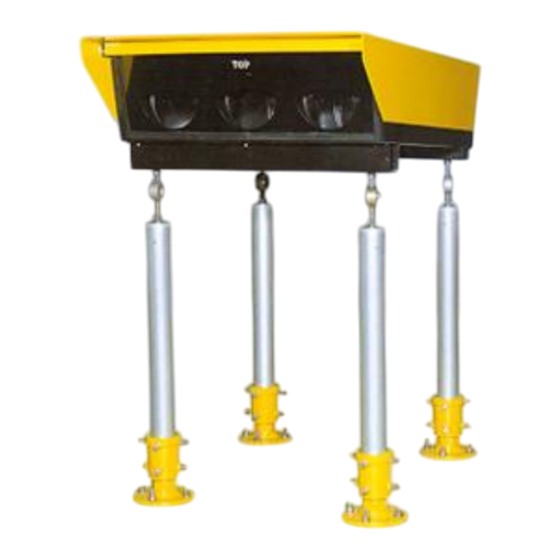
Specification & Operation Manual PAPI 600 7. Transportation and storage 7.1 Storage All the light units are supplied in the pack of a separate box. The mark of contents should be located on the outside of the packing box in an appropriate way. - Page 20 Specification & Operation Manual PAPI 600 Fig.8-1 The picture of the Precision approach path indicator Value Creating Partner YOUYANG...
- Page 21 Specification & Operation Manual PAPI 600 Fig.8-2 The mounting drawing of the Precision approach path indicator Flexible conduit Steel cover Base plate plate Base can Isolation transformer Value Creating Partner YOUYANG...
- Page 22 Specification & Operation Manual PAPI 600 Fig.8-3 The assembly drawing & material list of the Precision approach path indicator Value Creating Partner YOUYANG...
- Page 23 Specification & Operation Manual PAPI 600 PART NAME Q’TY Body cover Filter Filter support Inner lens Gasket Front cover support Front gasket Front glass Front cover Halogen lamp Reflector support Reflector assembly Aiming device support Filter fixture Body 2-pole plug...
- Page 24 Specification & Operation Manual PAPI 600 Approx 5m Approx 20m Stake #2 Theodolite PAPI Unit Stake #2 Value Creating Partner YOUYANG...
Need help?
Do you have a question about the PAPI 600 and is the answer not in the manual?
Questions and answers