
Related Manuals for YOUYANG PAPI 400

Summary of Contents for YOUYANG PAPI 400
- Page 1 USER’S MANUAL OPERATING & MAINTENANCE Precision Approach Path Indicator (2 Lamp)
-
Page 2: Table Of Contents
Operating and Maintenance Manual PAPI 400 CONTENTS 1. General 2. Compliance 3. Environmental Requirements 4. Detailed Specifications 5. Installation 6. Maintenance 7. Transportation & Storage 8. The Lists of Parts and Drawings... - Page 3 Operating and Maintenance Manual PAPI 400 Safety Instructions Safety precautions: Operating and maintenance personnel should refer to ICAO Airport Services Manual Part 9, “Airport Maintenance Practices” and to FAA Advisory Circular AC 150/5340-26 “Maintenance of Airport Visual Aid Facilities” for instruction on safety precautions.
- Page 4 (2) year from the date of delivery to the original purchaser. Within the frame of this warranty YOUYANG accept to replace the defective item free of charge, ex works. Operational failure or breakage resulting from lamp burnt out, improper...
-
Page 5: General
Operating and Maintenance Manual PAPI 400 1. General The PAPI units to be provided shall comply with ICAO photometric performances required for a Precision Approach Path Indicator system except when otherwise stated herein. PAPI system or APAPI system give pilots visual information for safe approach procedure of aircraft. - Page 6 Operating and Maintenance Manual PAPI 400 4.2 Photometric characteristics The photometric characteristics of lights are in accordance with the requirement of ICAO and FAA specification as follows. Main beam angle Type of Minimum beam Direction of light Color lights intensity...
- Page 7 Operating and Maintenance Manual PAPI 400 4.4.8 For each lamp one feeding cable made of synthetic rubber insulated, (AWG 12)flexible cable, polychloroprene sheathed with factory moulded 2 pole plug in accordance with FAA specification L-823, fig.1.a, and protected by a stainless steel reinforced flexible conduit for its run outside the PAPI unit, down to the transformer housing base cover.
-
Page 8: Installation
Operating and Maintenance Manual PAPI 400 5. Installation 5.1 Location The location of PAPI is as per ICAO as following figure 5-1. The distance of PAPI system from the threshold will be determined by approach slope angle, possible obstacle in approach zone, accordance ILS system, most demanding aircraft...etc. - Page 9 Operating and Maintenance Manual PAPI 400 Fig.5-2 Standard size of the concrete plinth 5.2.2 Mounting method 1) According to Fig. 5-2 mark position of base plate and anchor bolt on concrete plinth. 2) Make holes for 16 anchor bolts on concrete plinth.
- Page 10 Operating and Maintenance Manual PAPI 400 Fig. 5-3 Setting Sleeve Upper rod Setting sleeve Lock bolt Lower rod 8) Remove body cover of the unit and put the unit on 4 assembled legs. Fix the unit on the road by using washer and nuts.
- Page 11 Operating and Maintenance Manual PAPI 400 Fig. 5-4 Leg assembly Part name Base plate Breakable coupling Anchoring Leg Bolt for breakable coupling Nut for breakable coupling Fixing bolt for rod Setting sleeve Bolt for fixing body 10 Lock bolt of Setting sleeve...
- Page 12 Operating and Maintenance Manual PAPI 400 5.3 Wire connection Fig.5-6 Wiring diagram 5.4 Setting elevation angle 5.4.1 Required special tool - PAPI Clinometer (Aiming device): 1Set Fig.5-7 PAPI Clinometer set (aiming device) Clinometer Level support Spirit level 5.4.2 Recommended standard The angle of approach is typically 3 degree but that can be changed according to local airfield site situation.
- Page 13 Operating and Maintenance Manual PAPI 400 Fig.5-8 Typical position and angle of PAPI system (In case of 3 degree as approach angle) 5.4.3 Method of setting angle 1) Release 2 toggle switches of rear side of PAPI Unit and remove body cover of the unit.
- Page 14 Operating and Maintenance Manual PAPI 400 6) Position the clinometer on ② clinometer position on level support as Fig. 5-11 and on clinometer, set required approach angle on PAPI unit as Fig. 5-10. Fig.5-10. Example of angle setting of Clinometer (In case setting angle is 1°)
-
Page 15: Maintenance
Operating and Maintenance Manual PAPI 400 PAPI Unit-Top view Fig.5-11 Position of spirit level and clinometer on level support ① Rear position of spirit level on level support ② Clinometer position on level support ③ Front position of spirit level on level support 6. - Page 16 Operating and Maintenance Manual PAPI 400 6.2 Preventive maintenance Preventive maintenance of the airfield lighting equipment is a very important in securing the safe operations of the aircraft. Preventive maintenance schedule table Semi- Emergen- Maintenance items Daily Weekly Monthly Annually...
- Page 17 Operating and Maintenance Manual PAPI 400 6.3 Troubleshooting The table hereunder states the causes and the solution of the failures. Failure Cause Solution - Lamp defective - Replace the lamp. - The lamp is not connected to - Connect to the circuit.
- Page 18 Operating and Maintenance Manual PAPI 400 7. Transportation and storage 7.1 Storage All the light units are supplied in the pack of a separate box. The mark of the contents should be located on the outside of the packing box in an appropriate way. The lights packed in the boxes should be stored in dust-free, dry places, and they can be stored using shelves, boxes, or freight carriages.
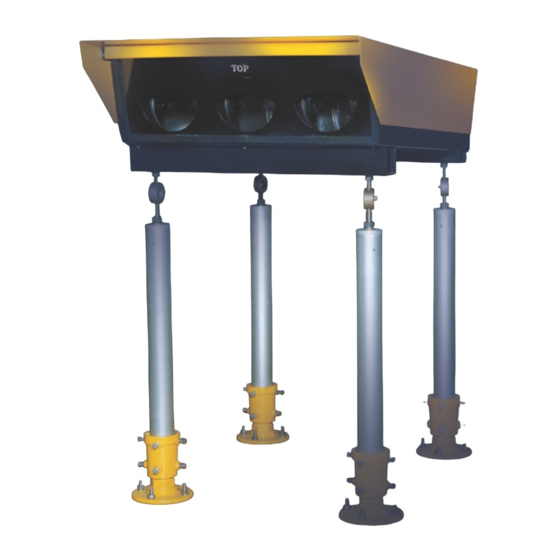
- Page 19 Operating and Maintenance Manual PAPI 400 Fig.8-1 The picture of the Precision approach path indicator Approx 5m Approx 20m Stake #2 Theodolite PAPI Unit Stake #2...
- Page 20 Operating and Maintenance Manual PAPI 400...
- Page 21 Operating and Maintenance Manual PAPI 400 Fig.8-2 The mounting drawing of the Precision approach path indicator Flexible conduit Base plate Steel cover plate Base can Isolation transformer Fig.8-3 The assembly drawing & material list of the Precision approach path indicator...
- Page 22 Operating and Maintenance Manual PAPI 400 Q’TY PART NAME STANDARDS Light body AL3T Front optic lens fixer AL3T Inner optic lens fixer AL3T Filter support AL3T Filter fixer AL3T Reflector fixer AL3T Rear cover AL3T Light body support (rear) AL3T...
Need help?
Do you have a question about the PAPI 400 and is the answer not in the manual?
Questions and answers