Advertisement
Quick Links
INSTALLATION INSTRUCTIONS
Quiet Flow Multi Exhaust Kit
Code: 8153
INSTALLATION
INSTALLATION
INSTALLATION
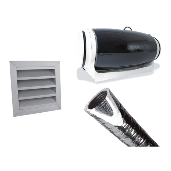
Kit Contents:
•
1x EMF150 silent inline exhaust fan with built in
back draft damper
•
1x 6 metre length R0.6 insulated flexible duct
•
1x 200mm x 200mm weatherproof external
aluminium louvre with plenum box and
150mm spigot
•
4m aluminium silver tape
•
4x cable ties
Compliance:
Complies with the following requirements in the
National Construction Code (2022) and Australian
Standards
•
F6 (light and ventilation)
•
F8 (condensation management)
•
J5 (building sealing)
Image 1. Intake grilles not included and shown for
schematic purposes. High Flow kit allows choice of
•
J6 (air conditioning and ventilation)
Image 1. Intake grilles not included and shown for schematic purposes.
Image 1. Intake grilles not included and shown for
intake grilles (sold separately)
•
AS1668.2
High Flow Kit allows choice of intake grilles (sold separately)
schematic purposes. High Flow kit allows choice of
•
AS4254.1 (flexible duct)
intake grilles (sold separately)
Step 1 – Install Fan. Fix fan securely to soffit of concrete slab,
Step 1 – Install Fan. Fix fan securely to soffit of concrete slab, timber beam or rafter.
timber beam or rafter. Position the fan between the proposed
Position the fan between the proposed intake grille location and the discharge point.
intake grille location and the discharge point. Ensure fan is
Step 1 – Install Fan. Fix fan securely to soffit of concrete slab, timber beam or rafter.
oriented in current direction (arrow on fan depicts direction of
Ensure fan is oriented in current direction (arrow on fan depicts direction of airflow and
Position the fan between the proposed intake grille location and the discharge point.
airflow and should point to discharge point). Fan should also be
should point to discharge point). Fan should also be installed in an accessible location (ie.
installed in an accessible location (ie. accessible area in roof
Ensure fan is oriented in current direction (arrow on fan depicts direction of airflow and
accessible area in roof space or via access panel). s
space or via access panel). s
should point to discharge point). Fan should also be installed in an accessible location (ie.
Step 2 – Connect 200mm dia. flexible ducting to both sides of fan using silver tape and
accessible area in roof space or via access panel). s
Step 2 – Connect 200mm dia. flexible ducting to both sides of
cable ties provided. Duct should be pulled as tight as possible with minimal bends. Avoid
fan using silver tape and cable ties provided. Duct should be
any bends to ductwork within 500mm on either side of fan. Any bend in ductwork within
Step 2 – Connect 200mm dia. flexible ducting to both sides of fan using silver tape and
pulled as tight as possible with minimal bends. Avoid any bends
500mm will impact fan performance.
to ductwork within 500mm on either side of fan. Any bend in
cable ties provided. Duct should be pulled as tight as possible with minimal bends. Avoid
duct work within 500mm will impact fan performance.
any bends to ductwork within 500mm on either side of fan. Any bend in ductwork within
Step 3 – Install exit 300x300mm Exit box and Louvre in wall or then connect flexible duct to
500mm will impact fan performance.
Step 3 – Install exit 300x300mm Exit box and Louvre in wall or
exit grille spigot.
then connect flexible duct to exit grille spigot.
Step 3 – Install exit 300x300mm Exit box and Louvre in wall or then connect flexible duct to
Step 4 – Connect Branch Take-off (200mm/150mm/150mm) to 200mm flexible duct.
exit grille spigot.
Step 5 – Measure approx. distance from branch take-off (BTO) to proposed intake grilles
Step 4 – Connect Branch Take-off (200mm/150mm/150mm) to 200mm flexible duct.
(or outlets) and cut 150mm insulated flex to length. Connect 150mm insulated flex to
Contents
●
1x Silent Inline Exhaust Fan (200mm diameter)
●
6m 200mm diameter flexible duct
●
6m 150mm diameter insulated flexible duct
●
BTO 8/6/6 Branch Take-Off (200mm/150mm/150mm)
●
1 x 300mm x 300mm Weatherproof louvre with box
(150mm spigot)
●
Cable ties (x8)
●
8 meters silver tape
Image 2. Multiple air intake outlets may be required
depending on size of grille.
Image 2. Multiple air intake outlets may be required depending on size
Image 2. Multiple air intake outlets may be required
depending on size of grille.
of grille.
Step 4 – Connect Branch Take-off (200mm/150mm/150mm) to
200mm flexible duct.
Step 5 – Measure approx. distance from branch take-off (BTO) to
proposed intake grilles (or outlets) and cut 150mm insulated flex
to length. Connect 150mm insulated flex to each 150mm outlet of
the BTO.
Step 6 - Depending on chosen intake grilles (Linear slot or
Shadowline diffuser), install plenum box of each grille and
connect to intake duct work prior to installing the ceiling.
Step 7 – Install ceiling diffusers or facias (linear slot grille) after
ceiling has been installed and painted. Follow installation
instructions for ceiling diffuser.
www.newtech.co.nz
Advertisement

Related Manuals for Newtech expella VENTILLATION 8153


Summary of Contents for Newtech expella VENTILLATION 8153
- Page 1 Step 5 – Measure approx. distance from branch take-off (BTO) to proposed intake grilles www.newtech.co.nz Step 4 – Connect Branch Take-off (200mm/150mm/150mm) to 200mm flexible duct. (or outlets) and cut 150mm insulated flex to length. Connect 150mm insulated flex to...
- Page 2 RANTY combustion gases does not occur. warranty from date of purchase TACT US: eton Rd, CONTACT US 981 1622 Email: info@expella.com.au www.expella.com.au 30 Mill Road, Whanganui sales@newtech.co.nz www.expella.com.au 0800 728 662 www.newtech.co.nz...
Need help?
Do you have a question about the expella VENTILLATION 8153 and is the answer not in the manual?
Questions and answers