
Related Manuals for TIS TRONIC 260U


Summary of Contents for TIS TRONIC 260U
- Page 1 Operating and installation manual Belkomin, Novaya Gozha village, 6, Grodno, Belarus...
- Page 2 Declaration of conformity № 0057/20 Temperature controller: TIS Tronic 260U meets the requirements of the relevant directives: 2014/35/UE low voltage Directive (LVD), 2014/30/UE electromagnetic compatibility Directive (EMC) Based on agreed standards: PN-EN 60730-1:2012 PN-EN 60730-2-9: 2011 product Marking CE: 05/2020...
-
Page 3: Safety
Safety warnings 1.1. General safety guidelines Please read the following rules before using it. Failure to follow these rules may result in personal injury and damage to the boiler and regulator. In order to ensure the safety of life and property, you must follow the precautions described in this manual. The manufacturer is not responsible for damages caused by improper use of the equipment or negligence on the part of the User. -
Page 4: General Information
2. General information Boiler regulator TIS Tronic 260u , is a modern electronic device intended to control operation solid fuel boiler and heating system The regulator controls a fan with speed control system, controls the operation of the circute. It has the function of preparing hot water (DHW) in SUMMER, WINTER mode with or without priority. -
Page 5: Control Panel
3. Control panel 3.1. Panel view and character designation Warning indicator informs about a malfunction, such as overheating, damage to the temperature sensor (short circuit, breakage) The CH pump diode - notifies of Central heating pump operation HUW pump diode-notifies about the operation of the hot water pump Fan indicator alerts you when the fan is in operation. -
Page 6: Display View And Description
3.2. Display view and description 3.3. Button functions Function - this button is used: in normal operation mode, to observe the operation of the heating and hot water modules, hold the button for 3 seconds to enter the controller Menu. In this mode, you can change parameters using the buttons that increase or decrease their value. -
Page 7: Regulator Maintenance
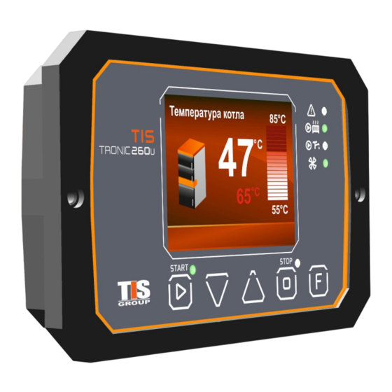
4. Controller maintenace 4.1 First launch When you turn on the controller using the switch located on the back panel, welcome screen will appear on the display, followed by one of the main screens of the controller. The controller is in inactive mode. This state is indicated by the yellow STOP light on the front panel, which is constantly illuminated. - Page 8 You can also change the settings on the main screens, in addition to displaying the current parameters,. The example screen (Fig.2) shows the boiler temperature readings parameters associated with it. Increasing and decreasing the set value boiler temperature performed using the buttons and is displayed on the screen (the value 65°C in the example of Fig.
-
Page 9: Initial Setup
4.2 Initial Setup You can enter the main menu by pressing button for 3 seconds The most important settings available in the main menu as follows: Boiler operation mode: Fan type Pumps start-up temperature The exhaust gas sensor activating Fuel shortage deteсting method Temperature scale... -
Page 10: Boiler Operating Mode
4.3 Boiler operation modes The controller has functions that allow you to work in three modes. Pre-configured in the standard operating mode the boiler oprates in two stages. Operation mode is changed in Boiler Settings - Operation mode (Standard, Brager Expert, Brager Expert... -
Page 11: Activating And Configuring The Huw Module
Brager Expert Mode -exhaust gases activates the foolowing parameters: Firing-up time-this parameter determines how long the exhaust gas temperature will be set to 300°C. This causes the fan to operate with the highest possible capacity, and results in faster fuel ignition. -
Page 12: Room Thermostat Settings
HUW working hours When temperature in the hot water tank drops by 5°C from the user-set temperature, the HUW pump is switched on again until the set temperature is reached in the tank. The HUW pump operating time parameter allows you to set the maximum time during which the HUW pump will try to reach the set temperature. -
Page 13: Setting The Extinguishing In The Boiler
4.6 Boiler quenching settings The controller is equipped with functions that control the boiler quenching process. As standard, without connected exhaust gases temperature sensor, the boiler quenching (switching off) is based on the boiler temperature. When exhaust gas temperature sensor (PT1000) is connected: function is activated that allows you to choose the method of the boiler switching off: If the chosen method based on the boiler temperature sensor readings, the boiler switches to quenching mode reaching up the value specified in the boiler temperature of switching off. -
Page 14: Parameter Meaning And Setting
4.7 Parameter values and settings You can enter the controller menu by holding the button for 3 seconds. The menu has been grouped into category sections, for easy navigation. The buttons allow navigate through the menu. To enter the "step forward"in the setting we are interested in, click the button and exit the General menu. - Page 15 Boiler Settings Boiler operating mode - The parameter allows you to set one of three boiler operating modes. Detailed configuration is described in section 4.3. Brager Expert exhaust gases - Firing up time - This parameter determines how long the boiler will operate at maximum fan power.
- Page 16 Fan type – regulator allows to select the type of the fan; the most popular versions are supported. Thus, you can be sure that the parameters of the fan performance will not have a so-called "dead band", in which, despite the changes in the parameters, no changes in the fan operation will be noticeable.
- Page 17 Brager Expert This menu contains advanced options for the Brager Expert algorithm. Detailed control and configuration are described in section 4.3. Software version The informative point shows the current version of the controller software installed. Reset to factory settings This option allows you to return to the default settings. Choosing language...
-
Page 18: Device Parameters
5. Device parameters 5.1 Technical data Power 230V/50Hz AC Relative humidity 30 - 75% 5 - 40°C Ambient temperature 100°C Temperature measurement range of sensors Output loading: Central pump HUW pump Power consumption (external devices not connected) 4,5W 5.2 Device parameters User Menu Fan maximum capacity Fan minimum capacity... - Page 19 Boiler settings Boiler operating mode Brager expert exhaust gases firing up time Fan slowdown threshold Boiler hysteresis Maximum boiler temperature Boiler shutdown temperature Pump start temperature Fan type Firing up time Boiler cooling temperature Exhaust gases temperature sensor Fuel shortage detection method Fuel shortage detection exhaust gases Fuel shortage detection time temperature...
-
Page 20: Alarms Description
6. Alarms description During the regulator operation, malfunctions and alarm conditions can occur, which are directly displayed on the main screen of the regulator (Fig. 5). In addition, alarm conditions are indicated by a pulsing red LED located on the right of the front panel. Using the button, we activate the screen displaying the list of occurred alarms (Fig. -
Page 21: Device Connecting And Preservation
7. Device connecting and preserving 7.1 Board view and connection diagram Symbol Designation Fan outlet CH pump outlet HUW pump output Emergency thermostat STB Central heating room thermostat Boiler temperature sensor HUW temperature sensor Exhaust gas temperature sensor Panel connector TR2_DISP Additional alarm (optional) Alternative slot for additional modules... -
Page 22: Connecting And Replacing Temperature Sensors
7.2 Connecting and replacing temperature sensors Before performing any repair work be sure to disconnect the regulator plug from the 220V power supply After disconnecting the power plug from the electrical outlet, unscrew the fixing screws on the back of the housing, and then remove the top cover. The controller sensors do not have polarity, it is not significant wiring sequence. -
Page 23: Boiler Temperature Protection And Hydraulic Connection Diagram
7.3 Boiler temperature protection and hydraulic connecting diagram 7.3 Boiler temperature protection and hydraulic connection diagram An additional thermal protection is connected in the regulator. It is an independent bimetallic sensor, which is triggered in case of the water temperature increase in the boiler. The sensor turns off the fan if the water temperature in the boiler rises above 90 °... -
Page 24: Fuse Replacement
7.4 Fuse replacement If the fuse blows, only replace it with a new one. The fuse holder is located directly on the control unit motherboard, on the back of the regulator housing. Please note that the new fuse must have the same rating as the broken fuse. -
Page 25: Table Of Contents
Contents Safety General safety guidelines Warnings Warranty General Information Control panel Panel view and symbol designation Display view and description Button functions Regulator maintenance First start Initial setup Boiler operating mode Activating and configuring the HUW module Room thermostat settings Setting the extinguishing in the boiler Parameter meaning and setting Device parameters... - Page 26 Warranty conditions and requirements Usage and warranty cases specified in the operating manual 1. The guarantee for the equipment is provided by BelKomin LLC in case of proper usage. Period is 24 months from the date of sale to the consumer, but not more than 36 months from the date of manufacture of the regulator.
- Page 27 3.R-T Datasheet Celsius Fahrenherit CT4 Boiler Sensor Degrees Degree (Ω) %/(K) ℃ ℉ (K) 1000 1030 1059 0.98 ±2.92 1105 1135 1165 0.96 ±2.74 0.93 1218 1247 1277 ±2.55 0.91 1338 1367 1396 ±2.35 0.88 1467 1495 1523 ±2.14 0.85 1603 1630 1656...
- Page 28 Notes ………………………………………………………………………………………………… ………………………………………………………………………………………………… ………………………………………………………………………………………………… ………………………………………………………………………………………………… ………………………………………………………………………………………………… ………………………………………………………………………………………………… ………………………………………………………………………………………………… ………………………………………………………………………………………………… ………………………………………………………………………………………………… ………………………………………………………………………………………………… ………………………………………………………………………………………………… ………………………………………………………………………………………………… ………………………………………………………………………………………………… ………………………………………………………………………………………………… ………………………………………………………………………………………………… ………………………………………………………………………………………………… ………………………………………………………………………………………………… ………………………………………………………………………………………………… ………………………………………………………………………………………………… ………………………………………………………………………………………………… ………………………………………………………………………………………………… ………………………………………………………………………………………………… ………………………………………………………………………………………………… ………………………………………………………………………………………………… ………………………………………………………………………………………………… ………………………………………………………………………………………………… ………………………………………………………………………………………………… ………………………………………………………………………………………………… …………………………………………………………………………………………………...
- Page 29 Device warranty card ……………..….…...…. ……………..….…...…. Symbol and serial number Manufacturing date ……………..….…...…. ……………..….…...…. (Date of Sale) (Seller signature and stamp) Warranty claims and regulator questions must be sent to the Manufacturer: 231741. Republic of Belarus, Grodno district, village Novaya Gozha, 6 www.belkomin.com...
Need help?
Do you have a question about the TRONIC 260U and is the answer not in the manual?
Questions and answers