Table of Contents
Advertisement
Quick Links
Advertisement
Table of Contents

Related Manuals for Pleasure-Way ASCENT


Summary of Contents for Pleasure-Way ASCENT
- Page 1 PLEASURE-WAY INDUSTRIES LTD. ASCENT OWNER’S MANUAL...
- Page 4 It will help you to better understand the many operational features of this recreational vehicle. After reading this manual, be sure to keep it in the motorhome as a reference. Your Pleasure-Way dealer will be glad to answer any further questions about the operation of your motorhome and the appliances.
-
Page 5: Table Of Contents
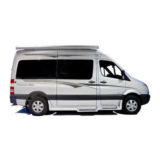
TABLE Of CONTENTS Warranties and Polices Safety 9-10 Motor Home Exterior 11-15 Motor Home Size Exterior Side Photos LP fill Valve Furnace Vent Driver’s Exterior Shower Driver’s Water Heater Vent Driver’s Side Sewer Dump Driver’s Side Fridge Vent Passenger’s Side Fresh water fill Passenger’s Side Exterior 110 volt plug Passenger’s Side Porch light Coach &... - Page 6 TV/DVD Theatre System User Guide 29-30 TS Bed Assembly Coach Specifications and Features Spare Tire and Carrier 32-33 Tire Safety 34-41...
-
Page 7: Warranties And Polices
36 months/36,000 miles/60,000 kilometers (which ever comes first) after the date of purchase by the original retail purchaser from an Authorized Pleasure-Way Dealer and shall be limited to making good, at our factory, any part or parts thereof upon return to the factory. - Page 8 Industries Ltd. will pay for the removal and reinstallation of Motorhome components only if absolutely necessary to perform Dodge warranty repairs. Pleasure-Way Industries Ltd. will not reimburse any costs in the removal and reinstallation of these components if it out of the warranty period;...
-
Page 9: Safety
All Pleasure-Way Motorhomes in Canada are CSA and CMVSS Certified, and may exceed the approved installation criteria. All Pleasure-Way Motorhomes in the United States are FMVSS certified and bear the R.V.I.A. seal of approval, and may exceed the individual state requirements. - Page 10 Filling the LP Gas Fuel Cylinder When you are filling the LP Gas Fuel Cylinder, ensure that all pilot lights have been extinguished and that there are no open flames present. Ensure that your vehicle is turned off. The main shut off valve is the electrical switch inside the exterior component compartment. NOTE: Ensure the propane system valve is fully shut when vehicle is in motion.
-
Page 11: Motorhome Exterior
MOTORHOME EXTERIOR Motorhome Dimensions and Capacities Your Motor Home is larger than your standard van or automobile, so please be careful when entering underpasses, garages, parkades, etc. DIMENSION 19’ 4” LENGTH BUMPER TO 590 cm BUMPER 20’ 8” LENGTH WITH TIRE & 630 cm CARRIER 9’... -
Page 13: Lp Fill Valve
LP Tank remote Fill and Breather Located under the driver side rear bumper of the vehicle, beside the tire carrier. NOTE: Only fill your propane tank to 80% capacity. Driver’s Side Furnace Vent Located on the driver’s side next to the water heater this vent is the exhaust and fresh air return for your furnace. NOTE: For maximum efficiency of your furnace this vent should be free from obstruction. -
Page 14: Driver's Side Sewer Dump
NOTE: Keep this vent clear from all obstructions. Driver’s Side Sewer Hose Compartment Located under the driver’s side running board. Access is through the sewer dump valve door, remove the white screw cap on the right hand side. Driver’s Side Sewer Dump Valves Located in the driver’s side running board door. -
Page 15: Passenger's Side Fresh Water Fill
Passenger’s Side Fresh Water Holding Tank Fill Located on the kitchen cabinet outside wall. Access this fill by opening the side exterior door. Note: Do not over fill the tank as it could damage the cabinet panel. Passenger’s Side Exterior 110-Volt Plug Located on the passenger’s side exterior rear panel, this plug will only function if power is supplied through the generator or shore power. -
Page 16: Travel Preparation
TRAVEL PREPARATION Before You Leave Prior heading off on your adventures, you should always check to ensure that: - the LP gas is off at the main valve - all black and gray waste water tanks are empty and closed. - all electrical cords and exterior hoses are stored back into their respective compartments - chassis fluid levels are at recommended levels - chassis tire pressure levels are at recommended levels... -
Page 17: Motorhome Systems
MOTORHOME SYSTEMS LP Gas System Your motorhome is equipped with a Liquid Propane (LP) gas system that provides fuel to the appliances (refrigerator, cook top, water heater, furnace, and generator.) The storage tank is located under the chassis, in between the hitch mounting plates. The main shut-off valve is operated electronically by the switch located in the driver’s outside component compartment. -
Page 18: Lp Remote Off/On
LP Remote Off/On Switch: Located in the Driver Side Component compartment. This switch activates the 12 volt electric solenoid. How to Use the LP Appliances; Turn your red key disconnect switch to the on position. (located under the driver side bed in the RL model or in the small driver side ottoman door in the TS.)Turn your electric propane valve switch to the on position. -
Page 19: Refrigerator
Refrigerator: Your vehicle is equipped with a Dometic three way fridge (LP gas, AC & DC). 1) Press the mode button till the word GAS appears . Press the thermometer button to the desired coolness (This may vary slightly with each fridge and weather conditions.) The fridge will go through the auto ignition process to ignite propane. 3) The DC or Battery symbol is used when the vehicle is in motion. -
Page 20: Fresh Water System
Fresh Water System The water system built into your motorhome provides full service similar to the system in your home. A 12-Volt self-priming pump draws pressurized water from the fresh water tank to all cold faucets and the water heater. An automatic pressure switch located in the water pump maintains a positive line pressure between 20 to 30 p.s.i. -
Page 21: Water Pump
Water Pump The Sure Flo water pump is located in the floor cabinet below the cooktop, The filter and the inlet connection are visible on the right hand side of the box. Activate the water pump using the switch at the bottom of the monitor panel above your microwave. Trouble Shooting: If the pump will not prime, please check: - to make sure there is water in the holding tank... -
Page 22: Shower
Waste System The Ascent is equipped with two waste tanks. 1) Black water tank located above the floor of the van directly under the toilet. Only the toilet water and solid waste enter this tank. -
Page 23: Winterizing
7) Open the termination valve on the solid waste holding tank. Black handle. Once this tank is empty, then open the valve for the gray waste tank Gray handle. A garden hose may be left running into the toilet with the valve open to further rinse the tank and sewer hose. - Page 24 4) Remove the water line from the inlet side of the water pump. (This is the clear plastic line going into the filter.) Connect a siphon hose to the inlet side of the water pump place the other end in a container RV Non toxic antifreeze. Turn on your water pump. NOTE: Siphon hose consists of 40”...
-
Page 25: Living Area Electrical System
Electrical Distribution Panel The Ascent is equipped with a Iota distribution panel that houses the breakers for the 110 volt system and the blade fuses for the 12 volt system. The distribution panel is located in the center of the main bench face in the TS. -
Page 26: Volt Reset Breakers
12-Volt Manual Reset Breakers and Converter Output Fuses Your motorhome has two manual re-setting breakers. If you have the optional electric rear sofa, you will have FOUR manual resetting breakers. Access to these breakers is through a compartment door found on the driver ottoman in the TS. These breakers have a 40, 30 and 15-amp capacity. -
Page 27: Battery Care
Battery Care Your auxiliary battery must be regularly cleaned and maintained at least once a month in order to provide a reliable and constant power source to your Motorhome. To ensure satisfactory battery performance, battery terminal cleanliness is essential. NOTE: Please see the DODGE manufacturer’s instructions for detailed maintenance recommendations. -
Page 28: Motorhome Interior
MOTORHOME INTERIOR Interior Cockpit Map Light Please follow the vehicle manufactures instructions for operating procedures. Refrigerator - Dometic Your Dometic refrigerator is designed for 3-way operation, using 12-Volt DC, 110-Volt AC and LP gas power. When the refrigerator is switched to AC or DC, the ammonia/water mixture is heated by a heating element instead of a burner. When your motorhome is stationary, it should be leveled for your refrigerator to provide the proper cooling. -
Page 29: Basic Tv Operation
TV and DVD (Optional) If your motor home is equipped with TV and DVD components, you will find these located in the rear entertainment center. These two components are powered by a 12-Volt power source. The TV and DVD are powered by a 12 volt inverter located in the cabinet above the TV.. - Page 30 A) 400 watt inverter B) Antenna booster E) AC Power Source Antenna Booster A) Green indicator light B) Booster Off/On switch. C) 12 volt power source 3 amp Inverter On/Off switch TV AC power cord Vizio 22” LED TV Full Digital TV Soft Touch Buttons: Source Menu...
- Page 31 Sherwood Decorative Dash Remote Propane Shut Off NOTE: Pleasure-Way Ind. Ltd. reserves the right to make product changes at any time with out prior notice or obligation. The bed area measurements may vary, due to components inside the vehicle.
- Page 32 Ascent Tire Carrier 1) Remove the Chrome Continental ring by releasing the key clip at the bottom of the ring and spreading it to come off the tire. 2) Remove the plastic tire cover by pulling up from the bottom. Unplug the license light by disconnecting the plugs.
- Page 33 4) Release and remove the safety pin, the locking clip and the carrier locking pin from the tire arm. 5) Lower the tire to the horizontal position. Use the 15/16” wrench to release the tire from the carrier arm. (Caution: Tire and carrier arm is heavy use assistance if possible.) 6) Refer to your Dodge Sprinter Manual for jacking and tire replacement instructions.
-
Page 34: Safety First-Basic Tire Maintenance
Index NHTSA homepage TIRE SAFETY Everything Rides On It Studies of tire safety show that maintaining proper tire pressure, observing tire and vehicle load limits (not carrying more weight in your vehicle than your tires or vehicle can safely handle), avoiding road hazards, and inspecting tires for cuts, slashes, and other irregularities are the most important things you can do to avoid tire failure, such as tread separation or blowout and flat tires. -
Page 35: Understanding Tire Pressure And Load Limits
Recommended tire inflation pressure Vehicle capacity weight (VCW–the maximum occupant and cargo weight a vehicle is designed to carry) Front and rear gross axle weight ratings (GAWR– the maximum weight the axle systems are designed to carry). Both placards and certification labels are permanently attached to the vehicle door edge, door post, glove-box door, or inside of the trunk lid. -
Page 36: Tire Tread
The recommended tire inflation pressure that vehicle manufacturers provide reflects the proper psi when a tire is cold. The term cold does not relate to the outside temperature. Rather, a cold tire is one that has not been driven on for at least three hours. When you drive, your tires get warmer, causing the air pressure within them to increase. -
Page 37: Tire Balance And Wheel Alignment
When they appear "even" with the outside of the tread, it is time to replace your tires. Another method for checking tread depth is to place a penny in the tread with Lincoln's head upside down and facing you. If you can see the top of Lincoln's head, you are ready for new tires. -
Page 38: Tire Fundamentals
system, known as the Uniform Tire Quality Grading System, provides guidelines for making relative comparisons when purchasing new tires. You also can use this information to inquire about the quality of tires placed on new vehicles. Although this rating system is very helpful when buying new tires, it is not a safety rating or guarantee of how well a tire will perform or how long it will last. -
Page 39: Speed Rating
Next number This three-digit number gives the width in millimeters of the tire from sidewall edge to sidewall edge. In general, the larger the number, the wider the tire. Next number This two-digit number, known as the aspect ratio, gives the tire's ratio of height to width. Numbers of 70 or lower indicate a short sidewall for improved steering response and better overall handling on dry pavement. -
Page 40: Utqgs Information
number of plies, the more weight a tire can support. Tire manufacturers also must indicate the materials in the tire, which include steel, nylon, polyester, and others. Maximum Load Rating This number indicates the maximum load in kilograms and pounds that can be carried by the tire. Maximum Permissible Inflation Pressure This number is the greatest amount of air pressure that should ever be put in the tire under normal driving conditions. - Page 41 The "LT" indicates the tire is for light trucks. Max. Load Dual kg(lbs) at kPa(psi) Cold This information indicates the maximum load and tire pressure when the tire is used as a dual, that is, when four tires are put on each rear axle (a total of six or more tires on the vehicle). Max.
Need help?
Do you have a question about the ASCENT and is the answer not in the manual?
Questions and answers