Table of Contents
Advertisement
Quick Links
Advertisement
Table of Contents

Related Manuals for Pleasure-Way 2022 REKON 4X4


Summary of Contents for Pleasure-Way 2022 REKON 4X4
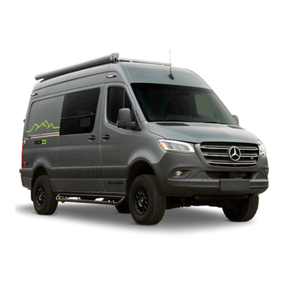
- Page 1 2022 REKON 4X4 Mercedes-Benz Sprinter 2500 4x4 OWNER’S MANUAL...
- Page 2 WARNING IT IS NOT SAFE TO USE COOKING APPLIANCES FOR COMFORT HEATING. Cooking appliances need fresh air for safe operation. Before Operation: Open overhead vent or turn on exhaust fan. Open Window. FAILURE TO COMPLY COULD RESULT IN DEATH OR SERIOUS INJURY. Unlike homes, the amount of oxygen supply is limited due to the size of the recreational vehicle, and proper ventilation when using the cooking appliances(s) avoids dangers of asphyxiation.
- Page 3 REKON 4X4 We know that you will enjoy your new Pleasure-Way and we wish you many miles of pleasant and carefree driving. Happy Travels!
-
Page 4: Table Of Contents
TABLE OF CONTENTS WARRANTY/POLICIES Furnace Vent SAFETY 120-Volt 30 Amp Power Occupant and Cargo Carrying Capacity City Water Connection Smoke Detector LP Compartment LP/Carbon Monoxide Detector Fresh Water Fill and Vent Fire Extinguisher Fresh Water Tank Drain GFCI Outlet Low Point Drain Refueling Fan-Tastic Vent®... - Page 5 WINTERIZING TOUCHSCREEN CONTROL PANEL Winterizing The Water Systems Home Page Optional Winterizing For Milder Climates DC Power/Coach Batteries Winter Storage Electrical Lighting Page LIVING AREA ELECTRICAL SYSTEMS Mechanical Page Voltage Chart Settings Page AC 110-120 Volt Power Diagnostics MOTORHOME INTERIOR Inverter/Charger Inverter Display/Control Panel Interior Cockpit Map Light...
-
Page 7: Warranty/Policies
Motorhome are followed properly. It is your responsibility and obligation to return your Motorhome in a timely manner to an authorized Pleasure-Way dealership for warranty service repairs. As the owner of the Motorhome, you are responsible for regular and proper maintenance performed in a timely manner in accordance with the Pleasure-Way and OEM manuals provided. - Page 8 (1) within 10 Examples include, but are not limited to: batteries, refrigerator, days of your discovery of a defect you notify Pleasure-Way or an microwave, roof air-conditioning, water pump, furnace, awning, TV, authorized Pleasure-Way dealership of the defect; AND (2) you fan, etc.
- Page 9 Limited Warranty, including, but not limited to, any other obligations or negligence or liabilities on Pleasure- “good will repairs” or any action of Pleasure-Way or its agents Way. There is no warranty of any nature made by Pleasure-Way or represenatatives shall be interpreted as extending, waiving beyond that contained in this Limited Warranty.
- Page 10 4. In the event that the Motorhome was not purchased as a hurricanes, airborne fallout, fire, rain, wind and all other new retail unit from an authorized Pleasure-Way dealer. environmental conditions, which may include but are not limited to, tree sap, tar, chemicals, oils, salts, ocean spray, 5.
- Page 11 It is advised that rental, revenue generating or business purposes, or any you store items accordingly. Pleasure-Way is not responsible Motorhome not registered and regularly used in the United for goods damaged while stored in exterior storage States or Canada.
- Page 12 • Foam used in cushions date by the original retail purchaser from an authorized Pleasure-Way dealer: any and all adjustments to compartment THREE (3) YEARS or 36,000 miles or 60,000 kilometers, door latches, hinges, light bulbs, fuses, remote and smoke whichever comes first, by the original retail purchaser from an detector batteries.
-
Page 13: Safety
All Pleasure-Way Motorhomes in the United States are FMVSS certified and bear operating instructions. the R.V.I.A. seal of approval, and may exceed the individual state requirements. -
Page 14: Lp/Carbon Monoxide Detector
LP/CARBON MONOXIDE DETECTOR A liquid propane (LP)/carbon monoxide (CO) gas detector is located near the floor level at the rear of the motorhome interior below the sink cabinet. This detector will detect liquid propane gas, carbon monoxide and other gases that are heavier than air. The detector is powered by the coach batteries and will only operate when the 12 volt battery disconnect switch is ON. -
Page 15: Refueling
REFUELING When you are refueling your fuel tank or your propane system, ensure that your vehicle and your main LP valve is shut off. Ensure your LP appliances (furnace, water heater) are shut off so ignition will not activate. Some appliances in your vehicle have auto ignition. Ensure the appliances are shut off so ignition will not activate. -
Page 16: Appliances
APPLIANCES It is not safe to use cooking appliances to heat the interior of the coach due to the danger of asphyxiation. It is recommended that you read all of the appliance owner / operating manuals prior to using the appliances. TRUMA PORTABLE FRIDGE Ensure the locking straps for the fridge are fully engaged and secured when the vehicle is in motion. -
Page 17: Motorhome Exterior
MOTORHOME EXTERIOR CHASSIS PAINT CODES (MERCEDES-BENZ SPRINTER CODES) Silver – 9744 | Steel Blue - 7755 | Charcoal Grey – 7992 Paint codes located on the driver seat base by opening the zipper flap and lifting the right hand flap. *Paint codes are subject to change please consult the driver seat base label.* MOTORHOME DIMENSIONS AND CAPACITIES 3.0 litre V6 Diesel | 188 HP Rating / 325 FT-LBS Torque... - Page 18 • The chassis manufacturer may make mechanical and option changes without Pleasure-Way Industries Ltd. incurring any obligation. • Pleasure-Way Industries Ltd. cannot be held responsible for changes made to an appliance supplied by another distributor or manufacturer. • Pleasure-Way Industries Ltd. cannot be held responsible for dealer installed options.
-
Page 19: Tire & Loading Information
TIRE AND LOADING INFORMATION The tire and loading information is located on the driver side door pillar. On this label you will find your tire size as well as cold tire pressure rating. Also found on this label is the seating capacity along with the occupant and cargo carrying capacity of your motorhome. -
Page 20: Power Awning
POWER AWNING Please refer to the manufacturer’s operating instructions for further information. The awning is located on the passenger side of the roof, this is a 10'6" Fiamma electric awning controlled by the switches located on the rear touchscreen control panel. The 12 volt battery disconnect switch must be in the ON position to operate the awning. -
Page 21: Waste Tank Compartment
WASTE TANK COMPARTMENT Please refer to the manufacturer’s operating instructions for further information. Located on the driver's side, mid body. This compartment gives you access to your toilet tank for dumping and filling purposes. The removable toilet tank will slide out of this compartment door. Allows disposal of the black water in the toilet into a sewer dump location. -
Page 22: 120-Volt 30 Amp Power
120 VOLT 30 AMP POWER The Rekon is equipped with a 30 amp power cord and outlet located on the driver's side mid body. When connecting this power cord it is recommended that you connect to the vehicle before connecting to a power source. Always ensure the power cord is locked onto the vehicle with the locking ring. -
Page 23: Fresh Water Fill And Vent
FRESH WATER FILL AND VENT The Rekon is equipped with a 40 gallon fresh water tank located under the raised floor in the rear of the coach. To fill this potable fresh water tank open the passenger rear door of the vehicle. Remove the potable water cap and insert a clean fresh water hose. -
Page 24: Fan-Tastic Vent® Fans
FAN-TASTIC VENT® FAN These dual bi-directional Fan-tastic Vent fans will quickly move air in and out of the coach. The two 14" vents are located on the roof-top, one close to the bathroom door that intakes and second above the bed/workstation that exhausts. This fan is equipped with a rain sensor that automatically closes when wet. -
Page 25: Maintaining Your Motorhome
MAINTAINING YOUR MOTORHOME It is recommended that you regularly maintain your Pleasure-Way Motorhome in order to get the maximum benefits from your unit. The life and performance of each component depends upon proper use, operation and maintenance. With a regular maintenance schedule you should be able to identify any components that may need attention, allowing you to have many years and miles of trouble-free traveling. -
Page 26: Travel Preparation
TRAVEL PREPARATION BEFORE YOU LEAVE WHILE IN MOTION Prior to heading off on your adventures, you should always check While in motion, set the refrigerator to operate in DC mode. to ensure that: Use of any other appliance is not recommended while the motorhome is in motion. -
Page 27: Motorhome Systems
MOTORHOME SYSTEMS LIQUID PROPANE GAS SYSTEM LP appliances are: Water Heater and Furnace Your motorhome is equipped with a Liquid Propane (LP) gas system that provides a fuel source to the appliances which are designed to use this gas for operation. The storage tank is located in the driver rear LP storage compartment. -
Page 28: Bbq Quick Connect
BBQ QUICK CONNECT The BBQ quick connect is directly connected to the RV LP system. It is equipped with it’s own shut-off valve (black handle). The quick connect is a regulated (low pressure) LP line that is supplied from the onboard LP tank. The BBQ quick connect works with the standard, full-flow male quick connect fitting. -
Page 29: Water Heater
WATER HEATER Please refer to the manufacturer’s operating instructions for further information. The water heater is located under the kitchen sink. Access to the working mechanism of the water heater is through the outside, vent door located mid-body on the driver side. TRUMA AQUAGO COMFORT PLUS (DLE60CP) ®... -
Page 30: Furnace
FURNACE Please refer to the manufacturer’s operating instructions for further information. Your vehicle is equipped with a Truma VarioHeat 11,500 BTU furnace. It is a LP gas and 12 volt appliance. The furnace is located under the driver side cabinet behind the grey tanks. To access the the furnace, remove the grey water tanks and the cover panel behind the grey tanks. -
Page 31: Fresh Water/Potable Water Tank
FRESH WATER / POTABLE WATER TANK The Rekon is equipped with a 40 gallon fresh water tank located under the raised floor in the rear of the coach. To fill this potable fresh water tank open the passenger rear door of the vehicle. Remove the potable water cap and insert a clean fresh water hose. -
Page 32: Grey Water Connection
GREY WATER CONNECTIONS The portable grey water tanks are stored inside the vehicle in the driver side rear cabinet lift and remove the cross bar to remove the tanks. Connect the Y connection (in the blue bag) to each of these ports and terminate the Y connection onto one of the portable grey water tanks. -
Page 33: Water Pump
WATER PUMP The water pump is located below the sink in the lower cabinet. The inline flow filter is located on the inlet side of the water pump. If the pump will not prime, ensure: there is water in the holding tank •... -
Page 34: Toilet
TOILET Please refer to the manufacturer’s operating instructions for further information. The Motorhome is equipped with a Thetford 200866SP cassette toilet. This toilet is connected into the water system and recieves water from the fresh water tank or city water. To turn the toilet bowl, use both hands to rotate to desired position (max. -
Page 35: Winterizing
WINTERIZING The Rekon was designed to be used in below freezing temperatures. However, if you plan to store your Rekon for the winter season and it will be exposed to freezing temperatures, follow the winterizing process below to protect the water system. If you plan to use the Rekon during the winter season please refer to the, “Winter Use Manual”... - Page 36 6. Open the exterior door to the Truma water heater. Turn the electrical switch to the OFF position. Open the water heater drain by lifting the black latch on the top of the yellow easy drain lever. Lower the drain lever until the water filter opens. 7.
-
Page 37: Optional Winterizing For Milder Climates
10. Remove the cassette from the toilet (step #3) and dump any residual water and antifreeze that may have accumulated during winterizing. Reinstall back into the toilet again for storage. 11. Open the low point drain valves on the red and blue water lines for 5 seconds and close them. -
Page 38: Winter Storage Electrical
WINTER STORAGE ELECTRICAL 1. Turn OFF the inverter by pressing the power directly on the inverter. The inverter is located in the first cabinet on the passenger side behind the fridge. 2. Fully charge your engine-starting and coach batteries. 3. Turn OFF the red key charge line disconnect switch, and remove the key. -
Page 39: Living Area Electrical Systems
LIVING AREA ELECTRICAL SYSTEMS The motorhome living area electrical system is designed for 110-120 VOLT OR AC EQUIPMENT convenience. It is capable of supplying the vehicle with at least two sources of power: 12 volt DC power and 110-120 volt AC Air Conditioner (if equipped) power. -
Page 40: Ac 110-120 Volt Power
AC 110-120 VOLT POWER A 25 foot, 30 amp power cord is provided in the rear storage area. To activate all power circuits, connect and lock the power cord to your coach in the driver side utility center and to an adequate 110- 120 volt power source. -
Page 41: Inverter Display/Control Panel
INVERTER DISPLAY / CONTROL PANEL This control panel is located on the inverter. Freedom XC Series INV-CHG Owners Guide.book Page 39 Monday, April 9, 2018 2:29 PM Inverter and Charger Operation Freedom XC Display Panel Status LED Indicators Indicator Definition Status LED indicators Indicates grid mode in which shore power is solid green... -
Page 42: Ac Electrical Distribution Panel
AC ELECTRICAL DISTRIBUTION PANEL Your motorhome is equipped with an AC distribution panel that houses the breakers for the 110-120 volt system. The distribution panel is located below the inverter. The breakers act like a household breaker; make sure the breaker is shut all the way off before you reset the breaker. -
Page 43: Charge Line Disconnect
CHARGE LINE DISCONNECT The charge line disconnect switch (red key) is in the passenger side front cabinet. The charge line disconnect switch (red key) controls the charge from the engine alternator and solar panels to the coach batteries. When the switch is ON, the coach batteries will charge from the engine alternator and solar panels. -
Page 44: Chassis Battery
Do not expose to excessive heat. Do not disassemble. Do not impact & crush. For warranty or replacement contact Pleasure-Way Ind. iron phosphate (LiFePO4) technology. Lithium iron phosphate Risque de choc électrique. Ne vous connectez pas en marche arrière ou en court-circuit. - Page 45 BATTERY MANAGEMENT SYSTEM The Eco-Ion Earth Smart batteries feature a built-in battery management system (BMS). The BMS automatically provides: • Short circuit protection • Low voltage protection • Cell balancing • Overcharge protection • Temperature protection CHARGING The Freedom XC inverter/charger and the Mastervolt DC-DC charger have been programmed to charge the coach batteries.
-
Page 46: Real Time Clock Fuse
WARNING: Do not charge your batteries below 32 degrees F or 0 degrees C. Charging the batteries when below these conditions Removal of cover plate by may cause damage to the lithium cells and shorten the See user guide before using unauthorized personnel will this battery. -
Page 47: Solar Panel Fuses
SOLAR PANEL FUSES MAIN SOLAR PANEL FUSE (30 AMP) The main 30 amp fuse for the solar panels is connected to the back of the red key disconnect. To access the back of the disconnect key remove the shelf section directly over top of the disconnect key. -
Page 49: Dcd Panel
DCD PANEL The DCD panel is located above the batteries. To access the DCD remove the black front panel above the batteries by removing the screws in the panel. The DCD contains the Block Fuses for the G12 panel, the inverter and the MasterVolt system. -
Page 50: Touchscreen Control Panel
TOUCHSCREEN CONTROL PANEL The touchscreen control panels are located on the side entrance cabinet facing out toward the door and on the rail above the sink. The touchscreen above the sink also has the red battery switch. The battery disconnect must be on to operate the screens. When you turn on the items in your coach with the touch screen, the chosen item will be lit in blue. - Page 51 LIGHTING QUICK ACCESS This area provides a short cut to your 5 most used lights. Go to SETTINGS icon for customization. Select the SCREEN SETTINGS button. This will bring up the DEFAULT BUTTONS section. Use the + and – buttons to adjust lighting options. Select a light button to turn ON or OFF lighting associated with the area.
-
Page 52: Dc Power/Coach Batteries
SOLAR CHARGER SETTINGS Touch the GEAR symbol to display the settings page for the solar controller. This includes: • Solar Charging Rate • History of Charge • Solar Charge Settings • Solar Charge Controller Maximum Ratings DC POWER / COACH BATTERIES BATTERY PANEL Indicates the state-of-charge of the batteries, battery voltage and the temperature of the batteries. -
Page 53: Lighting Page
LIGHTING PAGE Each lighting area has its own button in the LIGHTING page. Select a light button to turn ON or OFF lighting associated with the area. Buttons will display in light blue when activated. Buttons with a sliding bar are capable of dimming. The LIGHT MASTER button turns ON or OFF all the lights inside the vehicle. -
Page 54: Settings Page
SETTINGS PAGE The settings screen should show the coach model for your vehicle, it should be set to 2022 Rekon. The DIAGNOSTICS button will take you to the diagnostic screens. The SCREEN SETTINGS button will take you to the display setting screen. TEMPERATURE UNITS Select this button to change from FAHRENHEIT to CELSIUS. -
Page 55: Diagnostics
DIAGNOSTICS The DIAGNOSTICS main page will give you information on the MODULES for all appliance that are online in your coach. The ENTRY and MAIN LCD refer to the 10” display touch panels. A BLUE light signifies the module is online and working normally. A GREY light would indicate the module is offline and not operational. - Page 56 DCM3 This display allows you to monitor BATTERY HEALTH, BATTERY STATUS, BATTERY TEMPERATURE and CURRENT AMPERAGE DRAW. Max Discharge and Average Discharge is a cumulative number of amps drawn from the battery bank. This screen will give you an accurate account of what the battery status is, the amount of discharge and the number of cycles that the batteries have had.
-
Page 57: Motorhome Interior
MOTORHOME INTERIOR INTERIOR COCKPIT MAP LIGHT This is the Mercedes-Benz Sprinter map light system. Please follow the vehicle manufacturer’s instructions for operating procedures. This light is powered by the chassis (engine-starting) battery and prolonged use will deplete the engine starting ability. COOKTOP Please refer to the manufacturer’s operating instructions for further information. -
Page 58: Wet Bath/Gear Locker
HEATED WET BATH / GEAR LOCKER The heated wet bath / gear locker in the Rekon is a multi-purpose room. The bathroom comes equipped with a cassette toilet, showerhead, shower curtain, two removable shelves, 5 closet rods and a grey water drain. Lift and remove the shelves to access the rods underneath. -
Page 59: Solar Panel Package
SOLAR PANEL PACKAGE Please refer to the manufacturer’s operating instructions for further information. (for more touchscreen information see page 39, fuse information see page 35) Your vehicle can be equipped with 400 watt Carmanah solar panel package located on the roof. The GoPower solar panel info is displayed on the touchscreen on the HOME page. -
Page 60: Usb Charging Port
USB CHARGING PORT Your motorhome is equipped with USB charging ports. Each charging port features 2 USB slots that will fit a USB type A connector. The 12 volt battery disconnect switch must be ON to power the USB ports. The USB ports are protected by the DC Load Center G12 module. -
Page 61: Murphy Bed Layout
MURPHY BED LAYOUT The bed support cross members are located on the bottom of the passenger side Murphy bed. 1. Lift the lock on the front retainer lid for the bed cross members holder and rotate the lid out of the way. 2. -
Page 62: Rear Workstation
REAR WORK STATION 1. Lift the lock on the front retainer lid for the bed cross members holder and rotate the lid out of the way. 2. Lift the cross member out of the front retainer and slide the cross member out of the rear support. 3. -
Page 63: Jack & Jack Tools
JACK AND JACK TOOLS The jack and jack tools are located on the passenger floor area of the Sprinter cab, and in the lower right compartment under the passenger seat. The jack and jack tools are provided by Mercedes-Benz. Please refer to the Mercedes-Benz owner’s manual for jacking locations. -
Page 64: Tire Safety
TIRE SAFETY The following information has been acquired from the NHTSA website. EVERYTHING RIDES ON IT Therefore, as mentioned above, to avoid flat tires and other types of tire failure, you should maintain proper tire pressure, observe tire and vehicle load limits, avoid road hazards, and regularly Studies of tire safety show that maintaining proper tire pressure, inspect your tires. - Page 65 Manufacturers of passenger vehicles and light trucks determine 4. If the tire pressure is too low, note the difference between this number based on the vehicle’s design load limit, that is, the the measured tire pressure and the correct tire pressure. greatest amount of weight a vehicle can safely carry and the These “missing”...
- Page 66 TIRE BALANCE AND WHEEL ALIGNMENT TIRE FUNDAMENTALS To avoid vibration or shaking of the vehicle when a tire rotates, Federal law requires tire manufacturers to place standardized the tire must be properly balanced. This balance is achieved by information on the sidewall of all tires. This information identifies positioning weights on the wheel to counterbalance heavy spots and describes the fundamental characteristics of the tire and on the wheel-and-tire assembly.
- Page 67 INFORMATION ON PASSENGER VEHICLE TIRES The “M+S” or “M/S” indicates that the tire has some mud and snow capability. Most radial tires have these markings; hence, Please refer to the diagram below. they have some mud and snow capability. SPEED RATING The speed rating denotes the speed at which a tire is designed to be driven for extended periods of time.
- Page 68 ADDITIONAL INFORMATION ON LIGHT TRUCK MAXIMUM PERMISSIBLE INFLATION PRESSURE This number is the greatest amount of air pressure TIRES that should ever be put in the tire under normal driving conditions. UTQGS INFORMATION TREADWEAR NUMBER This number indicates the tire’s wear rate. The higher the treadwear number is, the longer it should take for the tread to wear down.
-
Page 69: Reporting Safety Defects
If you believe that your vehicle has a defect which could cause a crash or could cause you injury or death, you should contact Pleasure-Way immediately. PLEASURE-WAY CONTACT INFORMATION To contact Pleasure-Way, you may call us toll-free at 1-800-364-0189; go to www.pleasureway.com; or write to: Pleasure-Way Industries Ltd. 302 Portage Avenue Saskatoon SK, Canada S7J 4C6 Please refer to the vehicle/chassis owners’... -
Page 70: Maintenance Log
MAINTENANCE LOG MODEL: VIN#: YEAR: DATE PURCHASED: DATE WORK PERFORMED MILEAGE NOTES... - Page 71 DATE WORK PERFORMED MILEAGE NOTES...
- Page 72 3 02 P O R TAGE AV ENUE SA S KATOO N S K , CANADA S7J 4C 6 T EL : 8 0 0 .3 64.0189 FAX: 306.934.7085 WW W. P L E A SU R E WAY.C OM...
Need help?
Do you have a question about the 2022 REKON 4X4 and is the answer not in the manual?
Questions and answers