Advertisement
Quick Links
Q182JS
Joystick Controller
Feb 2014
The Joystick controller is a dual-axis controller that produces voltages as
Q182JS
the stick is moved up/down and left/right. Perfect for pitch bending or
controlling filter frequency and resonance as you play notes on the key-
board. The outputs can be used to control any parameter in the synthe-
sizer system.
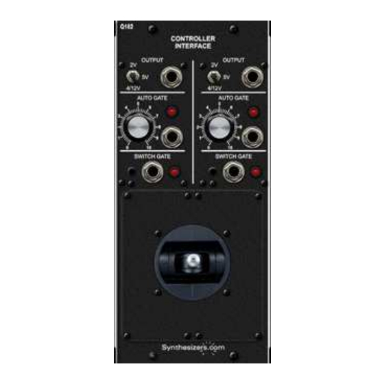
The Joystick controller uses our standardized Q182 dual-channel Control-
ler Interface module providing an Auto Gate, Switch Gate and a voltage
output range switch for each axis. The left side of the panel handles the X
axis (left/right) and the right side handles the Y axis (up/down).
The module can be mounted in a Box-style cabinet next to your keyboard
controller, or in a synthesizer cabinet just like any other module.
An Auto Gate signal is automatically created for each axis as the Joystick
is moved. This gate can be used to trigger sequencers and envelope
generators.
Switch Gate signals are produced by the panel buttons.
Q182JS Joystick Controller Specifications
Panel Size: 4.25"w x 8.75"h. (double-space)
Stick: 1.25" tall, Spring return to center on one or two axis.
Voltage Output: Selectable range - 5V, 2V, 4/12V
Auto Gate Output: 5V, adjustable position activation
Switch Gate Output: 5V, activated by manual buttons
Power: +15V@100ma, -15V@100ma, +5V@100ma
Advertisement

Related Manuals for Synthesizers.com Q182JS


Summary of Contents for Synthesizers.com Q182JS
- Page 1 This gate can be used to trigger sequencers and envelope generators. Switch Gate signals are produced by the panel buttons. Q182JS Joystick Controller Specifications Panel Size: 4.25"w x 8.75"h. (double-space) Stick: 1.25" tall, Spring return to center on one or two axis.
- Page 2 Q182JS Joystick Controller Feb 2014 This side handles This side handles the X axis the Y axis (left/right) (up/down) Output range. Voltage output. Set to 4/12V for One for X, +/- 2 semitone one Y range Auto Gate Auto Gate outputs trigger point.
-
Page 3: Features And Operation
Features and Operation Joystick controller mounted in a Box2 The Q182JS produces signals as the stick is moved up/down and left/right. The controller operates through the Q182 Con- troller Interface module to produce voltages and gate signals - one set for X axis movement, another set for Y axis move- ment. - Page 4 Q182JS Joystick Controller Feb 2014 Calibration Calibration is done at the factory and not required under normal circumstances. Only attempt these pro- cedures if you have the skills and a good digital voltmeter. We can perform this procedure for you.
- Page 5 Q182JS Joystick Controller Feb 2014 Q181 Controller Interface PCB Red Line Connector on flat cable to controller goes to pin 1 Jumpers shown in factory default location Range Toggle Switch 5V,2V,4/12V Bipolar Mode (Pitch Bend, zero center) Unipolar Mode (Modulation, zero end)
- Page 6 Q182JS Joystick Controller Feb 2014 Patch Ideas This is a common patch where the Joystick controller is used to pitch bend two oscillators. Voltage from the stick's X axis is added to the keyboard's pitch voltage at each oscillator. Pitch bend can also be ac- complished by using the Q174 MIDI Interface's ADD-IN input.
- Page 7 Q182JS Joystick Controller Feb 2014 In this patch, the Joystick controller is used as a pitch bender and the Switch Gate triggers an envelope generator for a special effect. Press the panel button to activate the Switch Gate. Q106 Oscillator...
- Page 8 Q182JS Joystick Controller Feb 2014 This patch shows the Joystick controlling a filter and the Auto Gate turning on noise modulation. As the stick is moved, the Auto Gate turns on according to the knob's position. That gate is then used to switch on a noise signal using a Q128 Switch.
Need help?
Do you have a question about the Q182JS and is the answer not in the manual?
Questions and answers