Advertisement
Quick Links
Q181RC
Ribbon Controller
Feb 2014
The Ribbon Controller produces a varying voltage as you move your finger
Q181RC
along the ribbon strip. Great for pitch bending, playing notes, controlling filter
frequency, or other parameters in the synthesizer system.
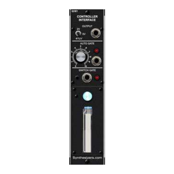
The Ribbon Controller uses our standardized Q181 single-channel Controller
Interface module providing an Auto Gate, Switch Gate and a voltage output
range switch.
The module can be mounted in a Box-style cabinet next to your keyboard con-
troller, or in a synthesizer cabinet just like any other module.
An Auto Gate signal is automatically created at a specific position along the rib-
bon. This gate can be used to trigger sequencers and envelope generators.
A 3-color LED can be programmed to change colors as the ribbon changes po-
sition or as the Auto Gate is activated.
Q181RC Ribbon Specifications
Panel Size: 2.125"w x 8.75"h. (single-space)
Ribbon: 2" x .5"
Voltage Output: Selectable range - 5V, 2V, 4/12V
Auto Gate Output: 5V, adjustable position activation
Switch Gate Output: 5V, activated by panel button
LED Colors: 3 primary colors (Red, Green, Blue)
LED Control: Down, Up, Power, or Auto Gate - user-configurable
Power: +15V@50ma, -15V@50ma, +5V@50ma
Advertisement

Related Manuals for Synthesizers.com Q181RC


Summary of Contents for Synthesizers.com Q181RC
- Page 1 This gate can be used to trigger sequencers and envelope generators. A 3-color LED can be programmed to change colors as the ribbon changes po- sition or as the Auto Gate is activated. Q181RC Ribbon Specifications Panel Size: 2.125"w x 8.75"h. (single-space) Ribbon: 2” x .5"...
- Page 2 Q181RC Ribbon Controller Feb 2014 Output range. Voltage output Set to 4/12V for based on the +/- 2 semitone range Ribbon position Auto Gate trigger point. Auto Gate output Activates based on (5V positive) Ribbon position Switch Gate Activated by...
-
Page 3: Features And Operation
Feb 2014 Features and Operation Ribbon mounted in a Box1 The Q181RC produces a voltage that varies as your finger is moved along the ribbon. The Ribbon controller operates through the Q181 Controller Interface module to produce volt- ages and gate signals. These signals may be used to control parameters in a synthesizer system. - Page 4 Q181RC Ribbon Controller Feb 2014 Calibration Calibration is done at the factory and not required under normal circumstances. Only attempt these pro- cedures if you have the skills and a good digital voltmeter. We can perform this procedure for you.
- Page 5 Q181RC Ribbon Controller Feb 2014 Q181 Controller Interface PCB Red Line Connector on flat cable to controller goes to pin 1 Jumpers shown in factory default location Range Toggle Switch 5V,2V,4/12V Bipolar Mode (Pitch Bend, zero center) Unipolar Mode (Modulation, zero end)
- Page 6 Q181RC Ribbon Controller Feb 2014 Patch Ideas This is a common patch where the Ribbon Controller is used to pitch-bend two oscillators. Voltage from the ribbon is added to the keyboard's pitch voltage at each oscillator. Use the 4/12V range position. The very center of the ribbon is 0.
- Page 7 Q181RC Ribbon Controller Feb 2014 In this patch, the Ribbon Controller is used as a pitch bender and the Switch Gate triggers an envelope generator for a special effect. When the Switch Gate panel button is pressed, the envelope will trigger.
- Page 8 Q181RC Ribbon Controller Feb 2014 This patch shows the ribbon controlling a filter and the Auto Gate turning on noise modulation. At a cer- tain position along the ribbon, the Auto Gate turns on according to the knob's position. That gate signal is then used to switch on a noise signal using a Q128 Switch.
Need help?
Do you have a question about the Q181RC and is the answer not in the manual?
Questions and answers