Advertisement
Quick Links
Advertisement

Related Manuals for VALUEPLANES LIPPISCH G108 KIT


Summary of Contents for VALUEPLANES LIPPISCH G108 KIT
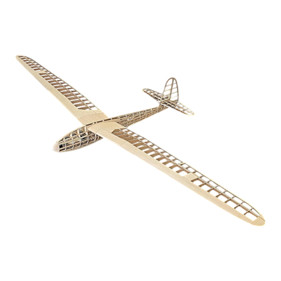
- Page 1 LIPPISCH G108 KIT BUILDING INSTRUCTION LASER-CUTTING KIT...
- Page 2 PECIFICATIONS Wingspan : 2750mm Length : 1400mm Flywing Weight : 1700g...
-
Page 3: Kit Features
KIT FEATURES Extremely lightweight. Fast-release wing and movable tailplane. Complete hardware pack. Extensive clear drawings and full-page colour instructions with hundreds of pictures . Only adhesives and coverings are required to complete the airframe. ... -
Page 4: Gerneral Information
GERNERAL INFORMATION E SURE TO READ THE SAFETY INSTRUCTIONS CAREFULLY BEFORE OPERATING YOUR MODEL • Always follow the procedures and settings recommended in the instructions. • If you are using remote-controlled model aircraft, helicopters, cars or ships for the first time, we recommend that you ask an experienced model pilot for help. -
Page 5: Building Instruction
BUILDING INSTRUCTION 1 FUSELASE ASSEMBLY Splice the base plate. 2) Glue the reinforcing plate to the motor base. 3) Assemble fuselage bulkheads in accordance with their respective part numbers (Keep parts number consistently forward). - Page 6 4) Glue magnets to Part A27 and install it onto the body. 5) Glue Part A29 to the lower section of the fuselage. 6) Glue balsa sheets to both upper and lower sections, as well as both sides of the fuselage (B1 is used for temporary positioning of partition bulkheads A6, A7, and A8;...
- Page 7 7) Glue tail parts A30 and A32 onto the fuselage. 8) Install the diagonally braced balsa sticks on the fuselage (utilizing balsa sticks for positioning reference).
- Page 8 9) Mount 2mm PVC sleeve into the structure. 10) Glue part A31 (ensure that fiber parts are placed in advance before A31 sealed on both sides). 11) Install vertical tail, glue balsa wood to leading edge followed by polishing, then glue 6MM balsa sheets to rear edge.
- Page 9 12) Superimpose multiple pieces of 6MM balsa and glue onto the fuselage and polish them accordingly. 13) Install elevator pulling connecting rod and clevis, seal fuselage sides with 3MM balsa sheets. 14) Assemble hatch cover, install magnets on part A26.
- Page 10 15) Glue 8MM balsa stick on top of hatch cover and polish it. 16) Glue 3MM balsa sheet on both sides of the fuselage. Glue B1 to the fuselage, ensuring that the balsa sheets are drilled to accommodate the servo extension wires.
- Page 11 18) Install B2 and B3, and insert the PVC sleeve. 19) Glue 8X8MM balsa strips to the leading edge and then glue 2MM balsa cover.
- Page 12 20) Trim off the base. 21) Mount the motor, glue and sanding balsa block as the nose. (A long shaft motor is required; additional bearing insalled on front-end motor shaft can be used for vibration reduction.)
- Page 13 22) Install the servos. 2 TAIL&WINGS ASSEMBLY 1) Construct the rudder.
- Page 14 2) Assemble the elevator ,using carbon tube positioning. 3) Polish both leading and trailing edges.
- Page 15 4) Assemble main beams according to their numbers, then glue wing ribs accordingly. 5) Install PVC sleeves for positioning with carbon tubes, then glue balsa strips onto main beams.
- Page 16 6) Glue reinforcing plates B27 on wing main girder splices, followed by installation of wing ribs. 7) Glue wing trailing edge and reinforce balsa strips. 8) Glue B33 to wing ribs and then joint 6X6MM balsa sticks.
- Page 17 9) Glue upper and lower wing coverings.(Servo extension wires must be installed advanced.) 10) Glue 8MM balsa on leading edge of wings and 2MM balsa cover in middle section of wings. 11) Polish front and rear edges of wings while using paper tape as a precaution against over-polishing.
- Page 18 12) Glue wing-tip and sand it. 13) Install aileron servo mount, glue 2MM balsa on the top, then strengthen by gluing pine block.
- Page 19 14) Assemble ailerons according to drawing specifications; polish leading edge into a triangular shape.
- Page 20 3 INTEGRAL CONSTRUCTION 4 FINISHED...
Need help?
Do you have a question about the LIPPISCH G108 KIT and is the answer not in the manual?
Questions and answers