Table of Contents
Advertisement
Quick Links
Advertisement
Table of Contents

Related Manuals for OHM CLEO MARK 2

Summary of Contents for OHM CLEO MARK 2
- Page 1 CLEO MARK 2 USER MANUAL...
- Page 2 Dynamic Range of 112dB un-weighted following standards: Digital gain adjustments from -15dB to 15dB MIDI system Exclusive (sysex) dump capabilities EMC Emission EN55103-1 (1996) Pre-loaded with system parameters for Ohm speakers EMC Immunity EN55103-2 (1996) Electrical Safety EN60065 (1998) Attractive styling Wellington Close •...
- Page 3 CLEO INTRODUCTION Congratulations on having purchased an OHM CLEO Mark 2 Please read this manual and familiarize yourself with the operation of your OHM CLEO Mark 2 before you attempt to power up the unit. For your own safety we recommend you take the time to read all the warnings and precautions on the page opposite and study the connection details to ensure correct usage and avoid any misuse which may invalidate your warranty.
- Page 4 FEATURES Active crossover filters with up to 48dB/Octave slopes to divide the audio spectrum into separate passbands for each transducer. Up to six outputs can be derived from either of the two inputs or a sum of both. Up to thirty eight bands of parametric or shelving equalization for smoothing system frequency response over the entire bandwidth.
-
Page 5: Front Panel
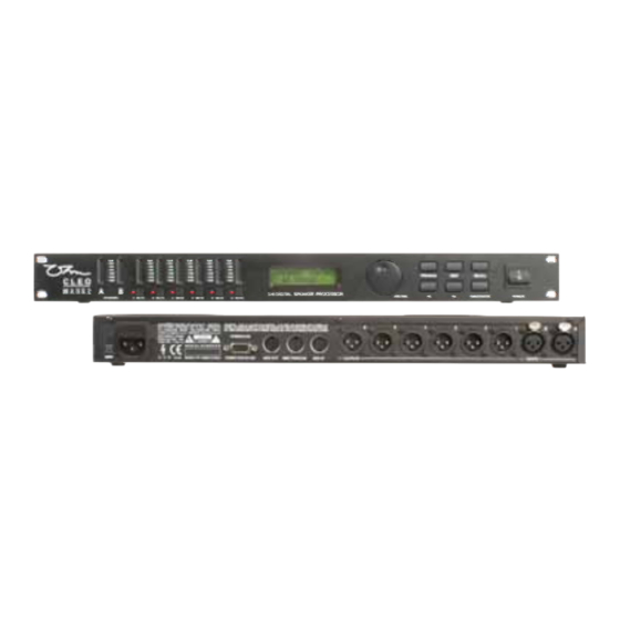
CLEO FRONT PANEL LED Input Barographs The Input Barographs respond to -30dB input and also indicate digital clipping. These show the input level: -30dB, -24dB, -12dB, -6dB, -3dB, LIMIT, CLIP. In CLIP LIMIT addition, the CLIP lights function both as analog input clip indicators and to show if there is clipping in the digital signal path. - Page 6 FRONT PANEL SAVE/RECALL Used to save edited programs to a new memory location and to RECALL save setups from the internal memories. To select a reconfigured program press the RECALL button on the front panel. From new the unit does not contain any preset programs but if the unit has been used before it may contain user preprogrammed setups.
-
Page 7: Operation
CLEO OPERATION PROGRAMS Program Saving A program can be stored in any one of the 60 available memory locations. Pressing SAVE/ENTER displays the Save screen with the last used program on the screen. Pressing either PREV/ENTER or turning the JOG DIAL enables the selection of the required memory for saving your new program. - Page 8 OPERATION RECALL 1 UNUSED Pressing RECALL a second time will recall the program. Delete Program Under Utilities mode, press either or turn the JOG DIAL clockwise, enter into the Delete Program Mode: UTILITIES ENTER TO DELETE DELETE PROG 1 MONITORS Choose the program to be deleted using the buttons.
- Page 9 CLEO OPERATION Press SAVE/ENTER to reconfigure the CLEO to the desired set up. Pressing any other keys will cancel the operation and return you to the previous configuration. 2.2 Mono Mode Switching to Mono configuration forces all Outputs to be routed from input A. Crossover frequencies are set to OUT, i.e.
-
Page 10: Stereo Link
OPERATION 2.4 LCR 2 Way Mode When using a derived centre cluster feed such as in LCR (Left, Centre, Right) installation, the configuration can be changed to a 3 channel 2 way configuration, where the centre is a sum of A & Outputs 1 &... - Page 11 CLEO OPERATION Offset parameters don’t have discrete selections, instead they have a range of numerical values such as gain, frequency or delay. These parameters can have offsets between them when the channels are linked. If any linked parameter reaches the value limit, none of the linked parameters will be able to move further in that direction.
-
Page 12: Crossover Mode
OPERATION 4. CROSSOVER MODE SETUP XOVER MODE BOTH This Utility allows the crossover slopes of the associated bands to be linked together for ease of setting. For example, when in ' Both ' mode changing the frequency of the Hi slope of an output channel set up as say 'low' band will also change the frequency of the Lo slope in the adjacent 'Mid' band output channel. - Page 13 CLEO OPERATION SECURITY LOCK OUTS Security Settings There are three levels of security for the unit, Lock Out OEM Lock Owner Lock . These are used to protect the parameters or programs from being inadvertently changed or tampered with by unqualified or unauthorized users.
- Page 14 OPERATION 6.5 Lock Set Up Mode A further press of either the PREV/NEXT buttons enters the Lock Set up mode Once in the Lock Setup Mode it is possible to navigate around the input and output screens as normal but with these important differences: Parameter values can no longer be changed.
- Page 15 CLEO OPERATION Pressing SAVE/ENTER saves the password and returns the display to the Utilities menu The unit will now not display locked parameters. If all parameters for a particular input or output channel have been locked the selection button for that channel will no longer display any associated screens as there are no parameters available to adjust.
-
Page 16: Delete Program
OPERATION DELETE PROGRAM To delete a program, press either or turn the JOG DIAL clockwise. SETUP DELETE PROG Choose the program to be deleted using the button, or JOG DIAL Press ENTER to delete the program. Pressing the PREV/NEXT button at any time will leave the Delete Program mode ENTER TO DELETE 1 MONITORS... - Page 17 CLEO OPERATION MASTER Enables transmission of all control changes to other devices on the same MIDI channel, e.g. To run CLEO in parallel for stereo applications. SETUP MIDI MODE MASTER THRU Allows the throughput of data received at the in socket to the MIDI out.
- Page 18 OPERATION The sending unit should now display the following message. MIDI DUMP PREPARING... If communication is successful then a progress percentage will be shown on the sending unit. When this reaches 100% the sending unit will return to the MIDI dump default screen and the MIDI dump...
- Page 19 CLEO OPERATION In LCD 2 way configuration outputs 1,3 and 5 are linked as are 2,4 and 6. When outputs are linked, the band name is derived from the channel assigned to the lower numbered output. Similarly, if the linked outputs are offset, the parameter value for the lower numbered output is displayed.
- Page 20 OPERATION 11.4 limiter Each output channel has a dedicated limiter that can be set to a threshold anywhere between -10dBu to +20dBu. OUT 1 & 2 AUX * LIMIT -6.2DBU There are two primary uses for limiters: One is for prevention of amplifier clipping and the second is to limit the amount of power transmitted to the transducers.
- Page 21 CLEO OPERATION Normally, the transducer delays are set first, then the overall delay for cluster alignment or delay tower set- up second. The following table shows the linkable channels in each mode. Mono 2 Channel 3 Way OUTPUT 3 Channel 2 Way None None None...
- Page 22 OPERATION OUT 5 & 6 HIGH * LO FREQ 8.00KHZ Note: If the Low edge filter frequency is raised beyond 16KHz, the channel output will be switched off. This is different to muting the output channel in that any signal assigned to this output will not indicate on the output meters.
-
Page 23: Rear Panel
CLEO OPERATION EQ Frequency The frequency of the EQ is adjustable from 15Hz to 16Khz in approximately 1/6 Octave steps. The screen below shows that this is the first EQ on Output2 (labeled as ‘High’). It has a frequency of 1Khz. If using a Low Shelving filter this would be the 3dB point. -
Page 24: Specifications
SPECIFICATIONS Input Section Input Impedance 10kOhm, electronically balanced Maximum Input Level +20dBu Input Gain +/-15dB variable in 0.1dB steps CMRR Better than 50dB (30Hz-20kHz) Input Connector XLR-3F or equivalent Output Section Output Impedance <50 Ohms, electronically balanced Maximum Output Level +20dBu into 600 Ohms or greater Output Gain +/-21dB, variable in 0.1dB steps... - Page 25 CLEO NOTES.
- Page 26 Wellington Close • Parkgate • Knutsford Cheshire • WA16 8XL • England Tel: +44 (0)1565 654641 • Fax: +44 (0)1565 755641 Email: info@ohm.co.uk • Website: www.ohm.co.uk...
Need help?
Do you have a question about the CLEO MARK 2 and is the answer not in the manual?
Questions and answers