
Related Manuals for U-F-M KATflow 170


Summary of Contents for U-F-M KATflow 170
- Page 1 OPERATING AND ATEX/IECEx SAFETY INSTRUCTIONS KATflow 170 – Aluminium Enclosure Clamp-On Ultrasonic Flowmeter for Hazardous Areas...
- Page 2 KATflow 170 Operating Instructions Official Katronic distributor for the Benelux : U-F-M b.v. Argon 3 4751 XC Oud Gastel The Netherlands Tel. +31 (0)165 855 655 E-mail info@u-f-m.nl www.u-f-m..nl © Copyright Katronic 2024 | Katronic® and KATflow® are registered trademarks of Katronic AG & Co. KG. Subject to...
-
Page 3: Table Of Contents
4 ELECTRICAL INSTALLATION 8 TROUBLESHOOTING 56 4.1 Electrical wiring 25 8.1 Measurement difficulties and error messages 56 4.2 Cabling and junction box 26 8.2 Data download difficulties 58 4.2.1 Signal cable parameters 26 9 TECHNICAL DATA 59 Operating Instructions KATflow 170 3/73... - Page 4 10.9 Clamp-on sensors: K1Ex, K4Ex 69 10.1 General 66 11 INDEX 70 12 APPENDIX A – Certificate of Conformity 71 10.2 Flowmeter 66 10.3 Quantity and units of measurement 67 13 Note 10.4 Internal data logger 67 4/73 Operating Instructions KATflow 170...
-
Page 5: Safety Instructions, Legal Requirements, Warranty, Return Policy
Operator keys are printed in bold typeface. 1.2 Safety instructions for the operator These safety instructions are applicable for sensor type K1Ex/K4Ex and KATflow 170 flowmeter installations in hazardous areas. • Do not install, operate or maintain this flowmeter without reading, understanding and following these operating instructions, otherwise injury or damage may result. -
Page 6: Languages/Translations
If the flowmeter has been diagnosed to have a problem, it can be returned to Katronic for repair using the Customer Return Note (CRN) attached to the Appendix of this manual. Katronic regret that for health and safety reasons we cannot accept the return of the equipment unless accompanied by the completed CRN. 6/73 Operating Instructions KATflow 170... -
Page 7: Legislative Requirements
Please use the Customer Return Note (CRN) in the Appendix 13 for return to Katronic. All products manufactured by Katronic are compliant with the relevant aspects of the RoHS Directive RoHS Directive. Operating Instructions KATflow 170 7/73... -
Page 8: Introduction
The KATflow 170 uses ultrasonic signals for measurement of the flow, utilising the transit-time method. The sensors of type K1Ex and K4Ex are equally suitable for use in hazardous areas. The KATflow 170 flowmeter can only be used with ATEX or IECEx certified sensors. -
Page 9: Approvals
II 2D Ex mbD 21 IP68 T80 °C - T120 °C X Tamb = -50 °C to +115 °C TRAC09ATEX21226X K4Ex 0008 2024 KATRONIC Coventry, UK 2804 Picture 3: Rating plate sensors K1Ex and K4Ex Operating Instructions KATflow 170 9/73... -
Page 10: Flowmeter
The KATflow 170 flowmeter is available in epoxy-coated aluminium or in stainless steel. Both versions are certified for use in hazardous area Zone 1 or 2. K1Ex and K4Ex sensors are connected to the KATflow 170 either directly or through an Ex e certified junction box with cables provided by Katronic. -
Page 11: Temperature Limits
Table 1: Temperature class K1Ex and K4Ex sensors 2.4.2 Flowmeter For KATflow 170 flowmeters located in Zone 1 or 2 hazardous areas the ambient temperature range is -20 ... +60 °C. The unit is manufactured to a degree of protection of IP66 (see Picture 4). -
Page 12: Special Conditions Of Safe Use
K1Ex and K4Ex sensors: • The transducers must only be used in conjunction with a flowmeter unit (e. g. KATflow 170) which conforms to the signal parameters and thermal protection conditions as outlines in the special conditions of safe use. -
Page 13: Installation
3.1.3 Identification of components The following items are typically supplied (please refer to your delivery note for a detailed description): • KATflow 170 ultrasonic flowmeter, • Clamp-on sensors (one pair for single-channel operation, two pairs for dual-channel operation), Operating Instructions KATflow 170... -
Page 14: System Configuration
• Calibration certificate(s) (optional). 3.2 System configuration The KATflow 170 flowmeter and K1Ex and/or K4Ex sensors can be installed in Zone 1 or 2 hazardous areas with or without a certified optional junction box depending on the required cable distances. -
Page 15: Clamp-On Sensor Installation
KATflow 170 INSTALLATION Picture 6: KATflow 170 in a 2-pipe 1-path configuration using optional junction boxes 3.3 Clamp-on sensor installation The correct selection of the sensor location is crucial for achieving reliable measurements and high accuracy. Measurement must take place on a pipe in which sound can propagate (see Section 3.3.1 Acoustic propagation) and in which a rotationally symmetrical flow profile is fully developed (see Section 3.3.2 Straight pipe lengths). -
Page 16: Straight Pipe Lengths
Select the measuring point at a location where the pipe cannot run empty. For a vertical pipe: Select the measuring point at a location where the liquid flows upward to ensure that the pipe is completely filled. Table 2: Recommendations for sensor mounting location 16/73 Operating Instructions KATflow 170... - Page 17 Disturbance source: 2 x 90°-elbow in different planes Inlet Outlet L ≥ 40D L ≥ 5D Disturbance source: T-section Inlet Outlet L ≥ 50D L ≥ 10D Disturbance source: diffuser Inlet Outlet L ≥ 30D L ≥ 5D Operating Instructions KATflow 170 17/73...
-
Page 18: Pipe Preparation
Clean dirt and dust from around the area of the pipework where the sensors are to be placed. • Remove loose paint and rust with a wire brush or file. • Firmly bonded paint does not necessarily need to be removed provided the flowmeter diagnostics indicate • sufficient signal strength. 18/73 Operating Instructions KATflow 170... -
Page 19: Sensor Mounting Configurations And Separation Distance
(see Picture 7, sketch 3). Negative separation distances may be suggested for Reflection Mode installations, but are not possible. In these cases, use Diagonal Mode or a larger number of passes. Operating Instructions KATflow 170 19/73... -
Page 20: Sensor Installation In Hazardous Areas
In order to obtain acoustical contact between the pipe and the sensors, apply a bead of acoustic coupling gel lengthwise down the centre of the contact area of the sensors. Picture 8: Application of acoustic coupling gel 20/73 Operating Instructions KATflow 170... -
Page 21: Correct Positioning Of The Sensors
The sensor positioning screen (see Section 5.3) allows fine adjustment of the sensor location. Picture 9: Correct positioning of the sensors Operating Instructions KATflow 170 21/73... -
Page 22: Sensor Mounting With Tension Straps
• Ensure that the narrower side of the clip is above and inside the wider side and that the two sides of the clip do not come into contact while tightening, as this will prevent the strap from being correctly tensioned. Picture 10: Metallic mounting straps 22/73 Operating Instructions KATflow 170... -
Page 23: Flowmeter Installation In Hazardous Areas
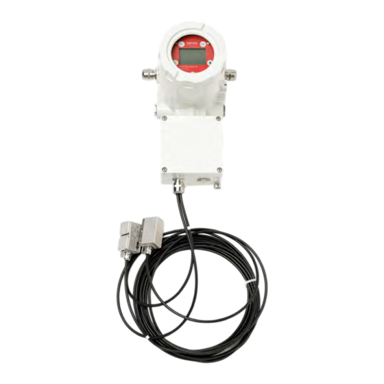
INSTALLATION 3.8 Flowmeter installation in hazardous areas The KATflow 170 is intended for 2ʼʼ mounting pole installations as shown in the following picture. Wall mounting is also possible but requires an optional bracket. Picture 11: K1Ex/K4Ex transducer and KATflow 170... -
Page 24: Flowmeter Installation
KATflow 170 INSTALLATION 3.9 Flowmeter installation 3.9.1 Outline dimensions Picture 12: Outline dimensions KATflow 170 24/73 Operating Instructions KATflow 170... -
Page 25: Electrical Installation
Please note that in order to supply the unit with mains power, the equipment must be protected by suitably sized switches and circuit breakers. 100 ... 200 V AC, 50/60 Hz 10 VA 9 ... 36 V DC 10 W Picture 13: Electrical connection diagram for the KATflow 170 flowmeter Operating Instructions KATflow 170 25/73... -
Page 26: Cabling And Junction Box
4.3 Cable glands The KATflow 170 housing features 2 x M20 cable entries for the sensor cabling (Ex e housing, square part of the housing, see Picture 12 and Table 5 for installation location) and 4 x M20 cable entries for power supply, communication and process input/output connections (Ex de housing, round part of the housing). -
Page 27: Equipotential Bonding
4.4.2 Flowmeter The KATflow 170 flowmeter must always be incorporated in the equipotential bonding system of the hazardous area installation. The explosion-proof housing of the KATflow 170 features a screw terminal outside the housing, which must be earthed locally (see Picture 12). The earthing conductor must have at least a cross-sectional area of 4 mm (11 AWG). -
Page 28: Operation
Picture 14: Keypad and display KATflow 170 The keypad of the KATflow 170 consists of five magnetic keys which can be operated from the outside of the enclosure using a magnetic pen. Hold the pen against the key area (white circle). The instrument acknowledges the activation of the key by turning the backlight off... -
Page 29: Keypad Key Functions
(upstream - against flow direction (U) and downstream - in flow direction (D)) Standard is U (Note: The switching function applies to ultrasonic board version 5.0 or higher) Table 6: Keypad key functions Operating Instructions KATflow 170 29/73... -
Page 30: Display Icons And Functions
150 V Data logger recording Off Data logger switched off Flashing Data logger almost full Function not used on KATflow 170 LCD backlight switched on Off LCD backlight switched off I/O processor error (internal display only) Off I/O processor works without errors Without strike-through: Speaker on Off... -
Page 31: Quick Setup Wizard
If 0 is entered and confirmed, an additional screen appears that allows entry of the circumference. Press ALT to delete characters at the current cursor position. Operating Instructions KATflow 170 31/73... - Page 32 ALT activates the scope function for further diagnosis. ⏵ switches between different signal dia-gnostic data. Confirm by pressing ENTER to obtain measurements. Note: Numbers shown are for indication only. Success! Table 8: Quick Setup Wizard 32/73 Operating Instructions KATflow 170...
-
Page 33: Measurement
Table 10: Main process value display in three-line display format 5.4.3 Totaliser The totaliser displays will only be shown when the totalisers are activated and a volume flow, mass flow or heat flow is selected as process value (middle line). Operating Instructions KATflow 170 33/73... -
Page 34: Diagnostic Display
RIGHT and DOWN keys. Table 13: Dual-channel measurement screen The dual-channel measurement screen is skipped if the flowmeter is not configured as a dual-channel device or if one of the channels is disabled. 34/73 Operating Instructions KATflow 170... -
Page 35: Math" Display
If a restart occurs that is not user initiated (for example power failure), the previous measurement session will be continued. Note that KATdata+ software cannot be used with this mode. Operating Instructions KATflow 170 35/73... -
Page 36: Commissioning
• K0L, K0N, K2T4, M, Q, Special (see “Start Measurement” below) Thermobuffer Select the type of the Thermobuffer ↓ (TB) • Type 1, Type 2, Type 3 • Special TB [please refer to the dedicated documentation] 36/73 Operating Instructions KATflow 170... - Page 37 ↓ (see above) SP1 – Sensor Only for special, unrecognised sensors Frequency SP2 – Wedge Only for special, unrecognised sensors Angle SP3 – Wedge Only for special, unrecognised sensors Sound Speed 1 Operating Instructions KATflow 170 37/73...
-
Page 38: Installation
Density 100 ... 2 000 kg/m Transv. Sound (Transverse sound velocity) Velocity 100 ... 3 500 m/s Heat capacity 0 … 10 J/(g*K) Lining Material Select from material list ↓ Thickness 1 ... 99 mm 38/73 Operating Instructions KATflow 170... - Page 39 Defines output behaviour in the event of error Select from list ↓ • Hold (hold last value, select hold time) • 3.8 mA • 21.0 mA • User (0 … 24.0 mA) Voltage Out Analogue voltage output Configure Individual module settings Operating Instructions KATflow 170 39/73...
- Page 40 Positive, Negative) Linear: Calculated maximum number of pulses per second, i. e. the maximum pulse rate in Hz • Min. Value: -10 000 10 000 • Max. Value: -10 000 30 000 • Damping: 1 ... 255 measurements 40/73 Operating Instructions KATflow 170...
- Page 41 -200 ... +600 °C – Pt 100 probe (Pt 100) Temperature (in °C) determined and read in by a • – Pt 1000 probe (Pt 1000) Temperature (in °C) determined and read in by a • – Operating Instructions KATflow 170 41/73...
- Page 42 1 ... 250 Baud Rate Selection of the baud rate 300, 600, 1 200, 2 400, 4 800, 9 600, 19 200, 38 400 baud Other In/Out Refer to Technical Support types System Instrument Info 42/73 Operating Instructions KATflow 170...
- Page 43 KATflow 170 COMMISSIONING Main menu Menu level 1 Menu level 2 Description/settings Model Code KATflow 170 (Serial number) Serial No. Example: 17024001 HW Revision Example: 4.00, 4.1 SW Revision Example: 6.06.01.0, 5.4 KAT Calculation Select Channel Select channel 1, channel 2 Low Flow ±...
- Page 44 Acknowledge error message with ENTER or quit the error display with ESC Further displays of temperature, data memory, etc. Data Logger Interval Enter logging interval in seconds: 0 ... 3 600 s 44/73 Operating Instructions KATflow 170...
-
Page 45: Serial Communication
1 and channel 2 (upstream and downstream) (see Section 6.8) • Exit screen: ESC • Sampling window +6 : UP • Sampling window -6 : RIGHT • Switching the display flow direction: ENTER Table 15: Menu structure KATflow 170 Operating Instructions KATflow 170 45/73... -
Page 46: Output Configuration
6.2 Output configuration The KATflow 170 has 5 Input/Output slot positions which can be configured with 5 individual I/O modules. Two slots occupy 4-wire terminals (1 to 4) whereas three slots use only 2-wire connection terminals (please refer to Picture 13). -
Page 47: Hart® Compatible Output
Table 16: Wiring Modbus RTU 6.2.3 HART® compatible output The KATflow 170 can also be configured with an optional module which responds to output commands conforming to the HART® protocol. Please refer to Customer Support for further information. HART® is a registered trademark of the HART Communication Foundation. - Page 48 < 500 Ω, 16 bit resolution, accuracy: 0.1 % of measured value Load • Passive: U = 9 ... 30 V, R < 500 Ω, 16 bit resolution, accuracy: 0.1 % of measured value Load Table 18: Wiring analogue current output 0/4 ... 20 mA 48/73 Operating Instructions KATflow 170...
-
Page 49: Analogue Voltage Output 0
Electrical characteristics • Galvanically isolated from main electronics and from other inputs and outputs • 2 Hz ... 10 kHz • U = 24 V, I = 4 mA Table 20: Wiring analogue frequency output (passive) Operating Instructions KATflow 170 49/73... -
Page 50: Digital Open-Collector Output
• Function: Alarm or Totaliser • Totaliser value: 0.01 ... 1 000/unit • Width: 1 ... 990 ms • U = 48 V, I = 250 mA • NO and NC contacts Table 22: Wiring digital relay output 50/73 Operating Instructions KATflow 170... -
Page 51: Input Configuration
The “Inputs/Outputs” menu will then allow the user to select the temperature input source, either Pt 100 temperature sensors or via a 0/4 … 20 mA input channel. Operating Instructions KATflow 170 51/73... -
Page 52: Heat Quantity Measurement
Where equipped, heat quantity (energy) and heat flow (energy flow) can be measured. If a heat quantity unit is specified for the process value, the KATflow 170 will ask the user for the specific heat capacity of the medium in J/g/K (for example 4.186 J/g/K for water). -
Page 53: Katdata+ Software
KATflow 170 COMMISSIONING 6.9 KATdata+ software Software can be provided for downloading the contents of the data logger and communication with the flowmeter. Operating Instructions KATflow 170 53/73... -
Page 54: Maintenance
(if installed) and the explosion-proof flowmeter housing. 7.1 Opening/closing the Ex d compartment The following instructions must always be carefully followed if opening the Ex d compartment of the KATflow 170 flowmeter. Ensure similar care is taken to close it when work is complete. - Page 55 To check and ensure, if necessary by rinsing or neutralising, that all cavities are free from such dangerous • substances, to enclose a certificate with the device confirming that is safe to handle and stating the product used. • Operating Instructions KATflow 170 55/73...
-
Page 56: Troubleshooting
WRITE ERROR MEASUREMENT STOPPED Hardware Too many internal ultrasonic Call Customer Support board communication errors REASON: COM ERRORS RESTARTING LOADING FAILED Hardware Failed to read a stored setup Call Customer Support from system memory 56/73 Operating Instructions KATflow 170... - Page 57 Customer Support! Table 25: Error list For all other error messages, please turn off and restart the flowmeter and if messages continue call Customer Support. Operating Instructions KATflow 170 57/73...
-
Page 58: Data Download Difficulties
• Check that the settings (baud, parity, word length, stop bits) are identical. • Use the supplied connectors – whether connecting to a 9-pin COM port or converting from serial communication to a Universal Serial Bus (USB). 58/73 Operating Instructions KATflow 170... -
Page 59: Technical Data
Table 26: Technical data pipe material *Note these values are to be considered nominal. Solids may be inhomogeneous and anisotropic. Actual values depend on exact composition, temperature, and to a lesser extent, on pressure and stress. Operating Instructions KATflow 170 59/73... -
Page 60: Technical Data Of Selected Fluids
Ethyl benzene 0.867 0.797 8.575 20 °C 20 °C 68 °F 17 °C 63 °F C8H10 Ether 0.713 985.0 3 389.8 4.87 0.311 3.346 C4H10O Ethyl ether 0.713 985.0 3 231.6 4.87 0.311 3.346 C4H10O 60/73 Operating Instructions KATflow 170... - Page 61 Propane (-45 to -130 °C) C3H8 °F 1 222.0 4 009.2 0.780 20 °C 20 °C 68 °F 1-Propanol C3H8O 1 170.0 3 838.6 0.785 2.718 29.245 20 °C 20 °C 68 °F 2-Propanol C3H8O Operating Instructions KATflow 170 61/73...
- Page 62 1.400 15.064 Turpentine 0.996 1 498.0 4 914.7 -2.40 1.000 10.760 Water, distilled 1 400.0 4 593.0 Water, heavy 1.025 1 531.0 5 023.0 -2.40 1.000 10.760 Water, sea Table 27: Technical data of fluids 62/73 Operating Instructions KATflow 170...
-
Page 63: Dependence Between Temperature And Sound Speed In Water
5 033 109.4 1 534 111.2 1 535 5 036 113.0 1 536 5 040 1 538 5 046 114.8 116.6 1 538 5 049 5 053 118.4 1 540 120.2 1 541 5 056 Operating Instructions KATflow 170 63/73... - Page 64 206.6 1 545 5 069 1 544 5 066 208.4 210.2 1 543 5 063 5 063 212.0 1 543 1 538 5 046 220.0 230.0 1 532 5 026 240.0 1 524 5 000 64/73 Operating Instructions KATflow 170...
- Page 65 4 003 460.0 1 200 3 937 470.0 1 180 3 872 480.0 1 160 3 806 3 740 490.0 1 140 500.0 1 110 3 642 Table 28: Temperature and sound speed in water Operating Instructions KATflow 170 65/73...
-
Page 66: Specification
0 ... 99 s Transit time measurement rate 100 Hz (standard) Output update time 1 s, faster rates on application Calculation functions Average/difference/sum/maximum (dual-channel use only) Operating languages Czech, Dutch, English, French, German, Italian, Romanian, 66/73 Operating Instructions KATflow 170... -
Page 67: Quantity And Units Of Measurement
Instantaneous measured value, parameter set and configuration, logged data 10.6 KATdata+ software Functionality Download of measured values/parameter sets, graphical presentation, list format, export to third party software, online transfer of measured data Operating systems Windows 10, 11, Linux, Mac (optional) Operating Instructions KATflow 170 67/73... -
Page 68: Process Inputs
HART-compatible output: 4 process variables selectable (PV, SV, TV and FV) Analogue: 4 ... 20 mA passive, R Load 220 Ω, U = 24 V, accuracy: 0.1 % of measured value Further process outputs available on application. 68/73 Operating Instructions KATflow 170... -
Page 69: Clamp-On Sensors: K1Ex, K4Ex
Standard cable lengths 5.0 m The transducers are approved for use in hazardous areas classified as Zone 1 and 2. They are connected directly to the flowmeter or via extension cables and Ex-approved junction boxes. Operating Instructions KATflow 170 69/73... -
Page 70: Index
29, 34, 36, 45, 47, 49, 50 Wall thickness 15, 19, 21, 32, 37, 38 Modbus RTU 42, 46, 47, 67 Warranty 5, 6 Multiple sensors Wizard (Quick Setup Wizard) 31, 32, 36 Negative separation distance 70/73 Operating Instructions KATflow 170... -
Page 71: Appendix A - Certificate Of Conformity
Tel. +44 (0)2476 714 111 VAT No. GB 688 0907 89 Warwick Street Fax +44 (0)2476 715 446 Registered in England Coventry CV5 6ET E-mail info@katronic.co.uk Number 3298028 United Kingdom Web www.katronic.co.uk Registered office as shown Cert. No. 23ISO0338 Operating Instructions KATflow 170... - Page 72 2804): Name of Document Document Number Quality Assurance Notification – ExVeritas 23PQAN0339 Manufacturing Processes The marking of the ultrasonic flowmeter KATflow 170 includes the following: 2804 • • Gas groups: II 2G Ex db eb IIC T6 Gb • = -20 ... +60 °C The marking of the ultrasonic transducers K1Ex/K4Ex includes the following: •...
-
Page 73: Notes
KATflow 170 13 NOTES Operating Instructions KATflow 170 73/73...
Need help?
Do you have a question about the KATflow 170 and is the answer not in the manual?
Questions and answers