
Related Manuals for RECO CompactLine RM-351 C

Summary of Contents for RECO CompactLine RM-351 C
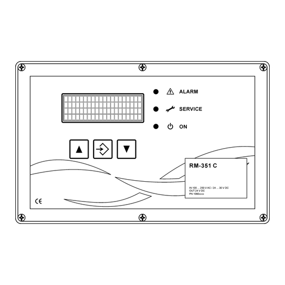
- Page 1 Operating and installation instructions R-IMC-BUS Filter control system RM-351 C CompactLine...
-
Page 2: Table Of Contents
Documentation RM-351 C Compact Line Contents 1 Safety instructions ............................. 3 2 Device description ............................. 3 3 Mechanical installation ..........................4 4 Electrical installation ..........................5 5 Settings ..............................12 5.1 Function in "as delivered" condition ....................12 5.2 Jumper on the RM-351 C board ....................13 5.3 Operating and display elements .................... -
Page 3: Safety Instructions
The intelligent I/O modules RM-V 8 and RM-V 16 handle distributed measuring and control tasks. The R-IMC-Bus (RECO – Inter Module Communication) employed for data transfer between the individual control components was developed specifically for use in industrial environments. Data exchange with the external components may optionally also be performed via Profibus, Profinet or Modbus. -
Page 4: Mechanical Installation
Documentation RM-351 C Compact Line 3 Mechanical installation RDN 10001384 10/11/2022... -
Page 5: Electrical Installation
Documentation RM-351 C Compact Line 4 Electrical installation Overview of the terminals and plug-in-module slots A-D Optional plug-in modules to extend the range of functions (slots A-D) Slot Module 4-20 mA module The module provides 2 analog outputs 4-20 mA or 0-20 mA or 2-10 V or 0-10 V. - Page 6 Documentation RM-351 C Compact Line Slot Module R-IMC bus-module For communication and data exchange between the RM-351 C controller and external devices. Profibus module For communication of the master (RM-351 C) with the slave modules via Profibus. Relay module 4 additional potential-free relay contacts. Terminal diagrams ...
- Page 7 Documentation RM-351 C Compact Line Relay outputs A1 ... A4, potential-free Output Factory-set function A1=0 The relay contact closes as soon as the supply voltage is applied to RM-351 C. It opens any time an alarm is present (Group Alarm). A2=1 Contact closes at control release and at downtime...
- Page 8 Documentation RM-351 C Compact Line Digital inputs E1 ... E8 Input Factory-set function E1=0 Release of the control when no signal is present E2=1 Cleaning on E3=1 Cleaning off (priority over Cleaning on) E4=1 Acknowledge alarm Cleaning pressure 100% (The 2/2-way valve of the cleaning pressure con- troller is always active.) No function...
- Page 9 Documentation RM-351 C Compact Line 4-wire connection Generally use shielded cables for 4-20mA signals and connect the shield to a PE ter- minal. Optional analogue outputs 4-20 mA / 2-10 V or 0-20 mA / 0-10 V For this function the 4-20 mA module must be plugged into slot A. The function depends on the position of the jumpers on the module and on the setting of parameter SBA.
- Page 10 Documentation RM-351 C Compact Line Optional R-IMC Bus interface For this function the R-IMC Bus module must be plugged into slot C. Optional display Modbus interface (graphic display) For this function the display Modbus module must be plugged into slot D. Differential pressure measuring lines RDN 10001384 10/11/2022...
- Page 11 Documentation RM-351 C Compact Line General information about the installation of the filter control Use shielded cables for all bus connections. Signal cables are not allowed to be installed parallel to power cables. All cable glands must be firmly tightened to make sure all cables are solidly enclosed and no water can enter.
-
Page 12: Settings
Documentation RM-351 C Compact Line 5 Settings 5.1 Function in "as delivered" condition The input and output functions of the controller are preset. The following parameters must be adjusted be- fore operating the RM-351 C: FAS 20 Number of valves FAS 21 Number of connected I/O modules RM-V 8 / RM-V 16 (if available) FAS 24 Valve output assignment key The RM-351 C works fully automatic after the number of the I/O modules, valves and the valve mode... -
Page 13: Jumper On The Rm-351 C Board
Documentation RM-351 C Compact Line 5.2 Jumper on the RM-351 C board Jumper Default set- Function ting To activate the terminating resistor of the RS-485 bus interface. (Jumper JMP 1 plugged in = termination resistor active) RDN 10001384 10/11/2022... -
Page 14: Operating And Display Elements
Documentation RM-351 C Compact Line 5.3 Operating and display elements in parametrisation mode* to select parameters and values (in upward key direction). in operating mode to call up the individual function data and text messages (in upward direction) F1 key to execute the action shown on the display under TF1 ... -
Page 15: Parameter Selection Level
Documentation RM-351 C Compact Line 5.4 Parameter selection level To view the parameters and their values the user must switch from the operating level to the parameter selection level. The and keys are pressed simultaneously until the green "ON" LED goes off (approx. 3 seconds). -
Page 16: Parameter Setting Level
Documentation RM-351 C Compact Line 5.5 Parameter setting level To change the value of a selected parameter or to activate and deactivate a parameter block the user must switch from the parameter selection level to the parameter setting level. To do this, press the EN- TER key until the green LED "ON"... -
Page 17: Short Instructions For Parameter Setting
Documentation RM-351 C Compact Line 5.8 Short instructions for parameter setting The ON LED indicates the current level of LED on Operating level the device. LED off Parameter selection level LED flashing Parameter setting level If no key has been pressed for 3 minutes the RM-351 C automatically returns from the parame- ter selection or the parameter setting level with the last values stored to the operating level. -
Page 18: Overview Of Menu Navigation
Documentation RM-351 C Compact Line 5.9 Overview of menu navigation RDN 10001384 10/11/2022... - Page 19 Documentation RM-351 C Compact Line RDN 10001384 10/11/2022...
- Page 20 Documentation RM-351 C Compact Line RDN 10001384 10/11/2022...
- Page 21 Documentation RM-351 C Compact Line RDN 10001384 10/11/2022...
- Page 22 Documentation RM-351 C Compact Line RDN 10001384 10/11/2022...
- Page 23 Documentation RM-351 C Compact Line RDN 10001384 10/11/2022...
- Page 24 Documentation RM-351 C Compact Line RDN 10001384 10/11/2022...
- Page 25 Documentation RM-351 C Compact Line RDN 10001384 10/11/2022...
-
Page 26: Parameter List
Documentation RM-351 C Compact Line 5.10 Parameter list Factory Display text Explanation setting Setting range Special functions — FH Funct. Code In. Function code entry – – Special functions can be acti- vated by entering function codes. — FH Cust. Code In. Customer code entry –... - Page 27 Documentation RM-351 C Compact Line Factory set- Display text Explanation ting Setting range 3 27 Whirl time 1 FAS 27 Whirl-up time in mode 1 5000 ms 120 ms … 5000 ms 34 3 28 Whirl time 2 FAS 28 Whirl-up time in mode 2 30 s 10 s …...
- Page 28 Documentation RM-351 C Compact Line Factory set- Display text Explanation ting Setting range Individual parameters 3 F19 Cln.PressControl Cleaning pressure controller see appendix 7 – 3 F20 FAS IntT.Ctrl. Pause time control see appendix 8 – 3 F21 FAS Clean.Monitr Cleaning monitoring see appendix 9 –...
-
Page 29: Fast Display Of The Most Important Current Operating And Parameter Values
Documentation RM-351 C Compact Line 5.11 Fast display of the most important current operating and parameter values The important operating and parameter values can be displayed in the operating mode of the controller. Briefly press the key several times to call up the following information in succession on the display. RDN 10001384 10/11/2022... - Page 30 Documentation RM-351 C Compact Line For more information on the operating messages, see section 8.4 "Operating messages" on page RDN 10001384 10/11/2022...
-
Page 31: Parameter Description And Explanation Of Function
Documentation RM-351 C Compact Line 5.12 Parameter description and explanation of function Parameter block FAS "Filter cleaning" Parameter FAS "Filter cleaning" The parameter block "Filter cleaning" can be activated or deactivated via parameter FAS. The parameter value is factory-set to 0 (= active). FAS = Text in display, lines 3 and 4 Explanation... - Page 32 Documentation RM-351 C Compact Line Parameter FAS 17 "Gate valve pulse time mode" The parameter is factory-set to 0 and is therefore not active. With the parameter setting FAS 17 =1 the pulse time of the gate valves is multiplied with factor 10 except with the option "Profibus on with protocol 1".
- Page 33 Documentation RM-351 C Compact Line the remaining entries of the cleaning table one after the other. Once you have completed all changes in the cleaning table, press the and keys simultaneously until the displayed text changes to enter the operating mode.
- Page 34 Documentation RM-351 C Compact Line FAS 25 = Text in display, lines 3 and 4 Explanation DP Clean.Start/Stop Cleaning works in start-stop mode. If the differential pressure reaches the Δp start value set via pa- rameter FDP1 15, cleaning is enabled until the differential pres- sure falls below the value FDP1 15 - FDP1 16 (Δp start value minus Δp hysteresis value).
- Page 35 Documentation RM-351 C Compact Line Parameter block FDP1 "Δp monitoring filter cleaning" Parameter FDP1 "Δp monitoring filter cleaning" Parameter block "Δp monitoring filter cleaning" can be activated or deactivated via parameter FDP 1. The parameter value is factory-set to 0 (= active). FAS = Text in display, lines 3 and 4 Explanation...
- Page 36 Documentation RM-351 C Compact Line Parameter FDP1 17 "Δp signal source" The source of the differential pressure measurement is set with parameter FDP1 17. FDP1 17 = Text in display, lines 3 and 4 Explanation No assignment No assignment I Input 2 Δp measurement via the 4-20 mA input 2 of the RM-351 C (terminal 41) I Input 3...
- Page 37 Documentation RM-351 C Compact Line Parameter FSP "National language" The display texts can be shown in different national languages. The text output is in German when the system is delivered. FSP = Text in display, lines 3 and 4 Explanation - Deutsch Text output German GB - English...
- Page 38 Documentation RM-351 C Compact Line Parameter FSB 1 "Operating hours counter" The operating hours counter mode can be set via parameter FSB 1. FSB 1 = Text in display, lines 3 and 4 Explanation Supply voltage ON The counter counts when mains voltage is present. Cleaning on The counter counts when cleaning is activated.
-
Page 39: Operating Modes
Documentation RM-351 C Compact Line 6 Operating modes 6.1 Continuous cleaning (Parameter FAS 25) Cleaning works continuously with the set pulse time (FAS 25) and the set pause time 1 (FAS 11) if pa- rameter FAS 25 is set to value 1. In the same way it works with pause time 2 (FAS 13) if parameter FAS 25 is set to value 2. -
Page 40: Downtimecleaning
Documentation RM-351 C Compact Line 6.4 Downtimecleaning If downtime cycles were set via parameter FAS 19, downtime cleaning is active for the set number of cy- cles with pause time 2 (FAS 13) when the enable is removed (1 signal is present at input 1). The following cases lead to the termination of an ongoing downtime cleaning. - Page 41 Documentation RM-351 C Compact Line All parametrized service and alarm messages remain active. If service or alarm messages occur, their cause must first be eliminated and the message must then be acknowledged in order to operate the sys- tem manually. In manual operation all downtime functions and outputs are switched off for safety reasons. In the valve test mode you can choose between the mode "Hd1"...
-
Page 42: Special Functions
Documentation RM-351 C Compact Line 7 Special functions 7.1 Functions for commissioning and service purposes For commissioning and service purposes, the following functions can be activated by entering the function code. Function code Explanation Code #### Master reset code for resetting all existing messages #### Commissioning code for displaying and enabling the hidden commissioning pa- rameters... -
Page 43: Text Messages On The Display
Documentation RM-351 C Compact Line 8 Text messages on the display 8.1 Program start Display Explanation The name of the program, the version number and the date of RM-351C ARM Versionsnummer the program release are displayed for approx. 2 seconds after !!! Booting !!! switching on the supply voltage. -
Page 44: Meaning Of The Signs In The Differential Pressure Display
Documentation RM-351 C Compact Line 8.3 Meaning of the signs in the differential pressure display Display Explanation Line 4 Minus sign (-) before the actual differential pressure value. DP current -250 Pa The differential pressure is negative. Display sample -250 Pa Check the following points: ... -
Page 45: Operating Messages
Documentation RM-351 C Compact Line 8.4 Operating messages In the "Automatic operation" operating mode of the filter control RM-351 C the following operating mes- sages are either displayed directly or they can be retrieved in sequence by pressing the key or the key. - Page 46 Documentation RM-351 C Compact Line Display Erklärung Line 4 FDP not active The following 2 text messages change every 2 seconds → Cont.Cleaning On Line 4 FDP1 function (Δp filter cleaning) is not active. Continuous cleaning is switched on. Line 4 (Cleaning is switched off.) Forced cleaning starts in ## T-Cln.in...
- Page 47 Documentation RM-351 C Compact Line Display Explanation Line 1: Parameter block FAS "Filter cleaning", window 1 Line 1 FAS Filter clean. TF1&F3= Setting menu Line 2 Line 2: The following 2 operating instructions change every 2 TF1= + / TF3= - Menu Line 2 seconds →...
- Page 48 Documentation RM-351 C Compact Line Display Explanation Line 1: Parameter block FDP1 "Δp monitoring" Line 1 FDP1 DP Monitoring TF2=More infos Line 2 Line 2: The following 3 operating instructions change every 2 TF1&F3= Setting menu Line 2 seconds → TF1= + / TF3= - Menu Line 2 No release...
- Page 49 Documentation RM-351 C Compact Line Further operating messages The following messages occur with different states of the filter system. Display Explanation Line 4 Cleaning is requested, but the control room or higher-level Clean. requested control system has not yet supplied an enable signal to the RM 351 C filter control system.
- Page 50 Documentation RM-351 C Compact Line Display Explanation Line 1 Cleaning control function FAS Filter clean.Hd1 Filter cleaning Manual operation, display 1 (also Hd2 or Hd3) Line 3 The valve with the displayed valve number is removed from FBS Bus Vent.No. off the cleaning process via the bus (skipped).
-
Page 51: Service And Alarm Messages
Documentation RM-351 C Compact Line Display Explanation Line 2 Operating note: By pressing the F2 key, you increase the I/O TF2 + TF4 Pulse V+1 module address by 1. By pressing the F4 key, you increase the valve number by 1 and trigger the pulse to control the valve (valve test in manual mode). -
Page 52: Acknowledgement Of Service And Alarm Messages
Documentation RM-351 C Compact Line Display Explanation Line 4 The displayed I/O module (RM-V 8 or RM-V 16) does not re- No response spond (bus communication). Line 3 Number of I/O module (RM-V 8 or RM-V 16) RMV Number Line 2 Operating note: If there are several messages, you can call up TF1=plus mes. -
Page 53: Overview Of All Available Functions
Documentation RM-351 C Compact Line 9 Overview of all available functions Abbreviat- Function / Parameter / Parameter Explanation Appendix ed desig- block number nation Analogue output assignment Parametrizable, freely selectable, analog output function Digital output assignment Parametrizable, freely selectable, digital output function Digital input assignment Parametrizable, freely selectable, digital input function Cleaning pressure controller... -
Page 54: Technical Specifications
Documentation RM-351 C Compact Line 10 Technical specifications Item Data Supply voltage 100 ... 240 V AC / 24 V ... 30 V DC Connected load Max. 150 VA / max. 150 W Signal inputs, digital 8 optocoupler inputs, 24 VDC internal High >15 V Low <... - Page 55 Documentation RM-351 C Compact Line Item Data Terminals Spring-cage terminal blocks with square opening Admissible cross section Single-wire: 22 ... 16 AWG / 0.5 ... 1.5 mm² Stranded: 22 ... 16 AWG / 0.5 ... 1.5 mm² Stripping length: 9 … 10 mm To open the tension spring-loaded terminals, use a screwdriver with a blade width of max.
Need help?
Do you have a question about the CompactLine RM-351 C and is the answer not in the manual?
Questions and answers
Why is the alarm showing in the power given