Table of Contents
Advertisement
Advertisement
Table of Contents

Related Manuals for RECO RM-BV4 Micro DP

Summary of Contents for RECO RM-BV4 Micro DP
- Page 1 Documentation RM-BV4 Micro DP Filter control...
-
Page 2: Table Of Contents
Documentation RM-BV4 Micro DP Contents 1 Safety instructions ........................... 3 2 Device description ........................... 3 3 Installation ............................... 4 4 Installation ............................... 5 4.1 Connection of the differential pressure measuring hoses ............. 7 5 Settings ..............................7 5.1 Function in "as delivered" condition ....................7 5.2 Indication and setting elements .................... -
Page 3: Safety Instructions
Documentation RM-BV4 Micro DP 1 Safety instructions Improper installation of the RM-BV 4 Micro DP or associated equipment may cause the failure of the device, serious or even fatal injuries. In addition to general safety rules for equipment in industrial... -
Page 4: Installation
Documentation RM-BV4 Micro DP 3 Installation RDN 10000662 24.01.2014... -
Page 5: Installation
Documentation RM-BV4 Micro DP 4 Installation Valve outputs It is possible to connect up to 4 solenoid valves featuring a rated voltage of 24 V DC to the terminals 9, 10, 11 … 16. Supply voltage There are separate controller models for the supply voltages 230 V AC, 110 V AC and 24 V DC. - Page 6 Documentation RM-BV4 Micro DP Alarm output The potential-free "Alarm" relay output, terminals 4 (NO), 5 (COM) and 6 (NC) is used for self- monitoring of the RM-BV 4 Micro DP. This output is energised during trouble-free operation. Following events will cause the relay contact to drop off: ...
-
Page 7: Connection Of The Differential Pressure Measuring Hoses
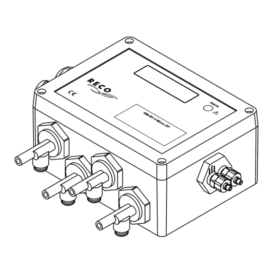
Documentation RM-BV4 Micro DP 4.1 Connection of the differential pressure measuring hoses Use the hoses with 4 mm internal diameter and 6mm outside diameter. Connect the connector marked with 3 stripes (black screw cap) with the raw gas side and the other connector (blue screw cap) with the clean gas side of the filter. -
Page 8: Indication And Setting Elements
Documentation RM-BV4 Micro DP The input „Start / Stop“ is factory-jumpered. The function of the input is described in chapter 4 „Installation“ under item If a different function is desired, the parameter setting of the RM-BV 4 Micro DP needs to be changed. -
Page 9: Parameter Setting
Documentation RM-BV4 Micro DP 5.3 Parameter setting RDN 10000662 24.01.2014... -
Page 10: Parameter List
Documentation RM-BV4 Micro DP 5.4 Parameter list Display text Meaning Factory setting Setting range 01 01 Tot.Valve.no. Number of valves 02 02 Pulse Time Pulse time of the cleaning 100 ms 30-900 ms valves 03 03 Interval T. 1 Interval time 1... - Page 11 Documentation RM-BV4 Micro DP Display text Meaning Factory setting Setting range 20 20 S.Run Hours Resets the service hour – No / yes delete ? counter to 0 h. 21 21 Relay funct. Relay function selection 22 22 Test mode Testing of the connected –...
-
Page 12: Operating Modes
Documentation RM-BV4 Micro DP 6 Operating modes 6.1 Standard cleaning For this, see the section 5.1 „Function in "as delivered" condition“.. 6.2 DP-controlled cleaning In "Operation" mode, the filter's current differential pressure ∆p is displayed in the text display. Cleaning starts when the differential pressure has reached the value „10 dP max“. -
Page 13: Dtc, Down Time Cleaning
Documentation RM-BV4 Micro DP 6.6 DTC, Down Time Cleaning Down time cleaning is activated differently, depending on the mode selected. With the DTC mode 1, down time cleaning is started via contact 7, 8 (fan stop: Contact 7, 8 must open). - Page 14 Documentation RM-BV4 Micro DP With DTC mode 3, down time cleaning is started if the differential pressure has fallen below the value „dP DTC Min“ (Parameter 17). after the value „dP DTC Min“ (Parameter 18) was first exceeded. The signal at input 7, 8 is not considered.
-
Page 15: Troubleshooting
Documentation RM-BV4 Micro DP 7 Troubleshooting Fault Possible causes Recommended action No display text message No mains voltage Check the power supply Fuse in device defective Replace fuse System EMERGENCY-STOP Check EMERGENCY-STOP actuated No valve activity and text Wiring to valves interrupted Check cables and electrical message "Alarm valve #"... -
Page 16: Text Messages
Documentation RM-BV4 Micro DP 8 Text messages 8.1 Operating messages Display Meaning After applying the voltage, the text message is displayed for approx. RM-BV 4 Micro+dP 1 second. The device powers up during this time and conducts a self- Version #.## test. -
Page 17: Additional Information
Documentation RM-BV4 Micro DP 8.2 Additional information Depending on the operating status, you can display further information by short pressing the or key. If no key is pressed within one minute, the display will automatically change to the original text message. -
Page 18: Technical Specifications
Documentation RM-BV4 Micro DP 9 Technical specifications Item Data Terminals Supply voltage Device version 230 V AC: 1 (L), 2 (N), 3 (PE) 230 V AC + / -10 % Device version 110 V AC: 1 (L), 2 (N), 3 (PE) 110 V ...
Need help?
Do you have a question about the RM-BV4 Micro DP and is the answer not in the manual?
Questions and answers