D-Link DGS-1008P Manual
- Quick installation manual (76 pages) ,
- User manual (21 pages) ,
- Quick install manual (8 pages)
Advertisement
Package Contents
This DGS-1008P package should include the following items:
- 1 x DGS-1008P
- 1 x AC to DC power adapter with power cord
- 1 x Wall mounting kit
- 1 x Quick Installation Guide
If any of the above items are damaged or missing, please contact your local D-Link reseller.
Hardware Overview
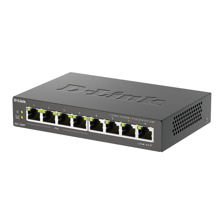
LED Indicators

Figure 1: Front panel LEDs
Table 1: LED overview
| # | LED | Status | Description |
| 1 | Power | Solid green | The switch is powered on. |
| Off | The switch is turned off. | ||
| 2 | PoE Max. | Solid amber | Indicates the total PoE power output of the switch has exceeded the Guard Band threshold of 53 watts. |
| Blinking amber | When the PoE power is available more than 7W, the PoE MAX LED will blink 5 seconds. | ||
| Off | Total power consumption is below Power Guard Band (53W). | ||
| 3 | PoE | Solid green | The port is providing power to the connected PoE-powered device. |
| Solid amber | The PoE power feed from this port has failed. | ||
| Off | There is no PoE-powered device connected to this port. | ||
| 4 | Link/ACT/Speed | Solid green | There is an active link negotiated at 1000 Mbps on this port. |
| Blinking green | There is traffic on the port. | ||
| Solid amber | There is an active link negotiated at 10/100 Mbps on this port. | ||
| Blinking amber | There is traffic on the port. | ||
| Off | There is no active link on this port. |
Front Panel Connectors

Figure 2: Front panel connectors
Table 2: Front connector description
| # | Interface | Description |
| 1 | Ports 1 - 4 | 10/100/1000 Mbps PoE-capable ports, used for connecting Ethernet devices and PoE-powered devices. |
| 2 | Ports 5 - 8 | 10/100/1000 Mbps non-PoE ports, used for connecting Ethernet devices. These ports cannot power PoE devices. |
Rear Panel Connectors

Figure 3: Rear panel connectors
Table 3: Rear connector description
| # | Connector | Description |
| 1 | Kensington Security Lock | Slot used to attach a physical Kensington security lock. |
| 2 | SWITCH GND | Screw used to secure a grounding wire to connect the switch to ground. |
| 3 | DC Power Input | Input jack for the power adapter. |
Hardware Installation
Installation Precautions
For safe switch installation and operation, it is recommended to:
- Visually inspect the DC power jack and make sure that it is fully secured to the power adapter.
- Make sure that there is proper heat dissipation and adequate ventilation around the switch.
- Install the switch in a site free from strong electromagnetic sources, vibration, dust, and direct sunlight.
- Not place heavy objects on the switch.
Grounding the Switch
The following steps explain the procedure for connecting the switch to a protective ground:
- Verify that the system is powered off.
- Remove the ground screw and place the #8 terminal lug ring at one end of the ground cable on top of the ground screw opening.
- Insert the ground screw back into the ground screw opening.
- Using a screwdriver, tighten the ground screw to secure the ground cable to the switch.
- Attach the terminal lug ring at the other end of the grounding cable to an appropriate grounding source.
- Verify that the connections from the ground connector on the switch to the grounding source are securely attached.
Attaching the Rubber Pads
The DGS-1008P comes with a strip with 4 adhesive rubber pads to place on the bottom of the device to prevent the switch from damaging the surface it is placed on. To attach the rubber pads, simply remove the rubber pads from the adhesive strip and stick one pad on each corner on the bottom panel of the switch.
Mounting the Switch to a Wall
The DGS-1008P can also be mounted to a wall for more convenient placement. Follow the instructions below for more information on how to mount the device to different types of walls.
Hard surface wall (e.g. cement, brick)
- Drill two holes that align with the keyholes on the back of the switch in the wall where you want to mount the DGS-1008P and place the two included nylon screw anchors into the drilled holes.
- Drive the two screws included in this package into the placed nylon anchors.
- Hook the mounting keyholes on the back of the switch onto the screws to secure the device to the wall.
Soft surface wall (e.g. wood, drywall)
- Drive the two screws included in this package into the soft surface wall where you want to mount the DGS-1008P so that they align with the keyholes on the back of the switch.
- Hook the mounting keyholes on the back of the switch onto the screws to secure the device to the wall.
Powering On the Switch
After connecting the switch to the network using a compatible category 5/6/7 UTP network cable, simply connect the switch to a power outlet to power the device.

This equipment can be connected only to PoE networks without routing to the outside plant.
The equipment power supply cord shall be connected to a socket-outlet with earthing connection.
TECHNICAL SUPPORT: dlink.com/support
Documents / Resources
References
Download manual
Here you can download full pdf version of manual, it may contain additional safety instructions, warranty information, FCC rules, etc.
Advertisement


Need help?
Do you have a question about the DGS-1008P and is the answer not in the manual?
Questions and answers