Huawei LUNA2000-(5-30)-S0 Manual
- Quick manual (24 pages) ,
- Quick manual (98 pages)
Advertisement
Product Overview
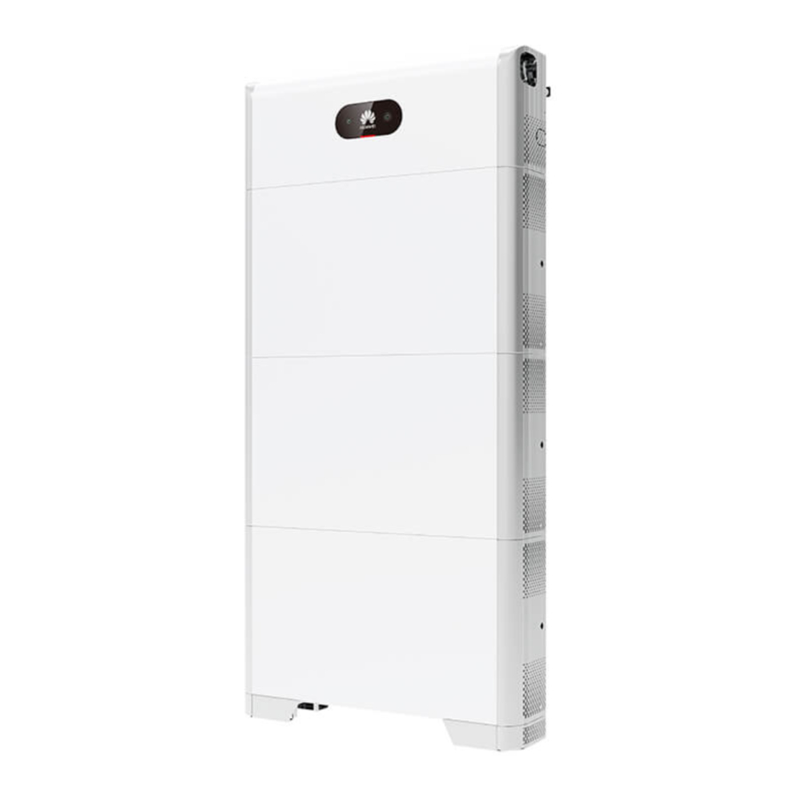
LUNA2000 Battery Appearance
The LUNA2000 battery is applicable to the grid-tied or off-grid systems of residential rooftop PV plants. It can store and release electric energy based on service requirements.
-S0 - Product Overview")
Note: The 15 kWh model is used as an example.
Power Control Module and Battery Expansion Modules
The LUNA2000 battery consists of a power control module and battery expansion modules. The power control module is 5 kW, and a battery expansion module has a standard capacity of 5 kWh.
-S0 - Power Control Module and Battery Expansion Modules - Part 1")
- Power control module
- Black start switch
- Battery terminals (BAT+/BAT–)
- COM port (COM)
- Battery cascading terminals
- DC switch (DC SWITCH) (B+/B–)
- COM port (COM)
- Fuse
- Ground point
- Battery terminals (BAT+/BAT– )
-S0 - Power Control Module and Battery Expansion Modules - Part 2")
- Battery expansion module
- Boss for alignment
- Battery cascading terminals (B+/B–)
- Battery cascading terminals (B+/B–)
- COM port (COM)
- Ground point
- Heat sink
- Ground point
Battery Capacity Description
The battery supports power and capacity expansion. Two power control modules can be connected in parallel. One power control module supports a maximum of three battery expansion modules.
-S0 - Battery Capacity Description")
Residential Rooftop PV System for Grid Connection
The residential rooftop PV system for grid connection generally consists of the PV module, LUNA2000 battery, grid-tied inverter, management system, AC switch, and power distribution box (PDB).
-S0 - Residential Rooftop PV System for Grid Connection")
Device Installation
Installation Requirements
Installation Environment
-S0 - Installation Environment")
Installation Space
-S0 - Installation Space")
Mounting Hole Dimensions
-S0 - Mounting Hole Dimensions")
Installing the Floor Support

Avoid drilling holes in the water pipes and cables buried in the wall.
-S0 - Installing the Floor Support")

The M6x60 expansion bolts delivered with the battery are mainly used for solid concrete walls and concrete floors. If other types of walls and floors are used, ensure that the walls and floors meet the load-bearing requirements and select the bolts by yourself.
Installing Battery Expansion Modules
- Install the battery expansion modules and power control module on the support.
NOTICE
- The following describes how to install the battery expansion modules for a 15 kWh model.
- The installation of battery expansion modules for 5 kWh and 10 kWh models is the same. One battery expansion module is installed for a 5 kWh model, and two battery expansion modules are installed for a 10 kWh model.
- Align the first battery expansion module with the support on the floor support.
-S0 - Installing Battery Expansion Modules - Step 1")
- Install the connecting pieces on both sides and tighten the four screws.
-S0 - Installing Battery Expansion Modules - Step 2")
- Install the remaining battery modules and power module from bottom to top. After installing a module, secure the left and right connecting pieces, and then install the next module.
-S0 - Installing Battery Expansion Modules - Step 3")
-S0 - Installing Battery Expansion Modules - Step 1")
-S0 - Installing Battery Expansion Modules - Step 2")
-S0 - Installing Battery Expansion Modules - Step 3")
- Secure the power control module to the wall.
-S0 - Installing Battery Expansion Modules - Step 4")
-S0 - Installing Battery Expansion Modules - Step 4")
Wall-mounted Installation
Mounting Hole Dimensions
-S0 - Mounting Hole Dimensions")
Installing the Support for Wall-mounted Installation

You need to purchase the mounting kits for wall-mounted installation by yourself.
-S0 - Installing the Support for Wall-mounted Installation")
Avoid drilling holes in the water pipes and cables buried in the wall.
Internal Electrical Connections of the Battery
NOTICE
- Connect cables in accordance with local installation laws and regulations.
- Before connecting cables, ensure that the DC switch on the battery and all the switches connected to the battery are set to OFF. Otherwise, the high voltage of the battery may result in electric shocks.
Installing an Internal Ground Cable
-S0 - Installing an Internal Ground Cable")
Installing Internal DC Terminals
-S0 - Installing Internal DC Terminals")
NOTE
- Internal electrical cables are delivered with the battery, see the Packing List in the packing case.
- The Amphenol terminal is used as the DC terminal between the power control module and the battery expansion modules.
Connecting Internal Signal Cables
-S0 - Connecting Internal Signal Cables")
External Electrical Connections of the Battery
Preparing Cables
NOTICE
- Connect cables in accordance with local installation laws and regulations.
- Before connecting cables, ensure that the DC switch on the battery and all the switches connected to the battery are set to OFF. Otherwise, the high voltage of the battery may result in electric shocks.
Prepare cables based on site requirements.
| No. | Cable | Type | Conductor Cross- Sectional Area Range | Outer Diameter |
| 1 | Ground cable | Single-core outdoor copper-core cable | 10 mm 2 | - |
| 2 | DC input power cable (inverter to battery and battery to battery) | Common outdoor PV cable in the industry | 4–6 mm 2 | 5.5–9 mm |
| 3 | Signal cable (inverter to battery and battery to battery) | Outdoor shielded twisted pair cable (8 cores) | 0.20–0.35 mm 2 | 6.2–7 mm |
Routing Cables Out of the Cable Hole
-S0 - Routing Cables Out of the Cable Hole")
Cut a cable hole based on the cabling mode, and route external cables through the cable hole.
NOTICE
Before connecting external cables, route the cables through the cable hole to avoid disconnecting after installation.
Installing a Ground Cable
-S0 - Installing a Ground Cable")
NOTE
- Ground a ground point of the power control module.
- Apply silica gel or paint around the ground terminal after the ground cable is connected.
Installing DC Input Power Cables
NOTICE
- You are advised to connect the battery terminals (BAT+ and BAT–) on the switch side to the inverter and connect the other side to the cascaded battery.
- The battery terminals use the Staubli MC4 positive and negative metal terminals and DC connectors supplied with the solar inverter. Using incompatible positive and negative metal terminals and DC connectors may result in serious consequences. The caused device damage is not covered under warranty.
Assembling DC Connectors
-S0 - Assembling DC Connectors")
Installing DC Input Power Cables
-S0 - Installing DC Input Power Cables")
- Use dedicated insulated tools to connect cables. Ensure that battery cables are connected to correct polarities. If the battery cables are reversely connected, the battery may be damaged.
Installing a Signal Cable
NOTICE
- When laying out a signal cable, separate it from power cables and keep it away from strong interference sources to prevent communication interruption.
- Ensure that the protection layer of the cable is inside the connector, that excess core wires are cut off from the protection layer, that the exposed core wire is totally inserted into the cable hole, and that the cable is connected securely.
- Use a plug to block the idle cable hole with the waterproof rubber ring, and then tighten the locking cap.
- If multiple signal cables need to be connected, ensure that the outer diameters of the signal cables are the same.
COM Port Pin Definitions
The COM port definitions on both sides of the power control module are the same. It is recommended that the COM port on the switch side be connected to the inverter and the COM port on the other side be connected to the cascaded battery.
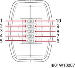
| No. | Label | Definition | Description |
| 1 | PE | Ground point on the shield layer | Ground point on the shield layer |
| 2 | Enable- | Enable signal GND | Connects to the enable signal GND of the inverter. |
| 3 | Enable+ | Enable signal+ | Connects to the enable signal of the inverter. |
| 4 | 485A1 | RS485A, RS485 differential signal+ | Connects to the RS485 signal port of the inverter. |
| 5 | 485A2 | RS485A, RS485 differential signal+ | |
| 6 | 485B1 | RS485B, RS485 differential signal– | Connects to the RS485 signal port of the inverter. |
| 7 | 485B2 | RS485B, RS485 differential signal– | |
| 8 | CANL | Extended CAN bus port | Used for signal cable cascading in battery cascading scenarios. |
| 9 | CANH | Extended CAN bus port | Used for signal cable cascading in battery cascading scenarios. |
| 10 | PE | Ground point on the shield layer | Ground point on the shield layer |
Connecting the Communications Terminal to the Inverter
-S0 - Installing DC Input Power Cables")
(Optional) Cable Connections in Cascading Scenarios
Cascading Networking
-S0 - Cascading Networking")
Cascading DC Input Connection
Prepare DC connectors and connect DC battery cascading terminals (BAT+ and BAT–) for cascaded batteries. For details, see section 4.4 "Installing DC Input Power Cables."
Connecting the Communications Terminal for Cascaded Batteries
-S0 - Connecting the Communications Terminal for Cascaded Batteries")
Connecting Cables to the Inverter
SUN2000-(2KTL-6KTL)-L1
-S0 - Connecting Cables to the Inverter - Part 1")
COM Port Pin Definitions
-S0 - Connecting Cables to the Inverter - Part 2")
| No. | Label | Definition | Description |
| 3 | 485B 2 | RS485B, RS485 differential signal– | Used for connecting to the RS485 signal ports of the battery. |
| 4 | 485A 2 | RS485A, RS485 differential signal+ | |
| 5 | GND | GND | Used for connecting to GND of the enable signal. |
| 6 | EN+ | Enable signal+ | Used for connecting to the enable signal of the battery. |
SUN2000-(3KTL-12KTL)-M1
-S0 - Connecting Cables to the Inverter - Part 3")
COM Port Pin Definitions
-S0 - Connecting Cables to the Inverter - Part 4")
| No. | Label | Definition | Description |
| 7 | 485A2 | RS485A, RS485 differential signal+ | Used for connecting to the RS485 signal ports of the battery. |
| 9 | 485B2 | RS485B, RS485 differential signal– | |
| 11 | EN | Enable signal+ | Used for connecting to the enable signal of the battery. |
| 13 | GND | GND | Used for connecting to GND of the enable signal. |
Verifying the Installation
Installing the Cover
After electrical connections are complete, check that cables are correctly and securely connected, install the external protective cover, and secure it using screws.
-S0 - Installing the Cover")
Verifying the Installation
| No. | Acceptance Criterion |
| 1 | The battery is installed correctly and securely. |
| 2 | The cables are routed properly as required by the customer. |
| 3 | Cable ties are secured evenly and no burr exists. |
| 4 | The ground cable is connected correctly and securely. |
| 5 | The battery switch and all switches connected to the battery are OFF. |
| 6 | The DC input power cables and signal cables are connected correctly and securely. |
| 7 | Idle terminals and ports are locked by watertight caps. |
| 8 | The installation space is proper, and the installation environment is clean and tidy. |
Power-On Commissioning
Connecting the Battery Supply
NOTICE
- After turning on the battery switch, power on the inverter. For details about how to power on the inverter, see the quick guide for the corresponding inverter model.
- If no PV module is configured, press the black start button.
Turn on the DC switch on the battery. After the battery is installed and powered on for the first time, the ring LED blinks for three circles. Observe the battery indicator to check the running status.
| Type | Status (Blinking at long intervals: On for 1s and then Off for 1s; Blinking at short Intervals: On for 0.2s and then Off for 0.2s) | Meaning | |||
| Running indication |  |  | N/A | ||
| Steady green | Steady green | Operating mode | |||
| Blinking green at long intervals | Blinking green at long intervals | Standby mode | |||
| Off | Off | Sleep mode | |||
| Blinking red at short intervals | N/A | Battery power control module environment alarm | |||
| N/A | Blinking red at short intervals | Battery expansion module environment alarm | |||
| Steady red | N/A | Battery power control module fault | |||
| N/A | Steady red | Battery expansion module fault | |||
| Battery system indication | N/A | ||||
 | Indicates battery level. One bar represents 10%. | ||||
| Steady red | The first three bars indicate the number of faulty battery expansion modules. | ||||
Battery Deployment
Download and install the FusionSolar app of the latest version by referring to the quick guide for the corresponding inverter model or the FusionSolar App Quick Guide. Register as an installer and create a PV plant or owner (skip this step if an account exists). You can obtain the FusionSolar App Quick Guide by scanning the QR code.

(Optional) Upgrading the Inverter and Smart Dongle
When the app connects to the inverter, a message is displayed, asking you to upgrade the inverter version. Smart Dongle V100R001C00SPC117 and later versions support LUNA2000 battery. But the Smart Dongle cannot be upgraded locally. You need to perform the upgrade through the management system. The upgrade procedure is updated in the Quick Guide. You can scan the QR code on the right to obtain the Quick Guide.

Quick Setup (New Deployment)
Log in to the FusionSolar app using the installer's account. Tap Quick Settings on the home screen to add the battery and set the battery working mode.
-S0 - Quick Setup (New Deployment)")
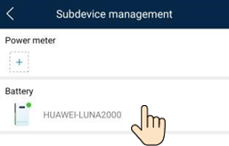
Adding a Device (Battery Expansion Scenario)
On the home screen, choose Maintenance > Subdevice management, select the battery model, and add batteries.
Setting Battery Control
On the home screen, choose Power adjustment > Battery control, and set the battery parameters and working mode.
-S0 - Setting Battery Control")
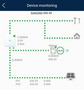
Battery Status Check
After the battery is added, tap Device monitoring on the home screen to view the running status, level, power, and charge and discharge status of the battery.
Maintenance and Upgrade
Battery Upgrade
When the network is connected, the app connection screen, tap >![]() File download in the upper-right corner. Then on the home screen, choose Maintenance > Upgrade device to upgrade the battery version.
File download in the upper-right corner. Then on the home screen, choose Maintenance > Upgrade device to upgrade the battery version.
-S0 - Battery Upgrade")
Storage and Recharging
The batteries need to be recharged for a certain period of storage. For details, see the user manual.
Fuse Replacement
If a fuse needs to be replaced, replace it by referring to the user manual.
Customer Service Contact Information
| Customer Service Contact Information | |||
| Region | Country | Hotline | |
| Europe | France | eu_inverter_support@huawei.com | 0080033888888 |
| Germany | |||
| Spain | |||
| Italy | |||
| United Kingdom | |||
| Netherlands | |||
| Others | For details, visit solar.huawei.com. | ||
| Asia Pacific | Australia | au_inverter_support@huawei.com | 1800046639 |
| Turkey | tr_inverter_support@huawei.com | N/A | |
| Malaysia | apsupport@huawei.com | 0080021686868/1800220036 | |
| Thailand | (+66) 26542662 (charged by local call) | ||
| 1800290055 (toll-free in Thailand) | |||
| China | solarservice@huawei.com | 4008785555 | |
| Others | apsupport@huawei.com | 0060-3-21686868 | |
| Japan | Japan | Japan_ESC@ms.huawei.com | 0120258367 |
| India | India | indiaenterprise_TAC@huawei.com | 1800 103 8009 |
| South Korea | South Korea | Japan_ESC@ms.huawei.com | N/A |
| North America | United States | na_inverter_support@huawei.com | 1-877-948-2934 |
| Canada | na_inverter_support@huawei.com | 1-855-482-9343 | |
| Latin America | Mexico | la_inverter_support@huawei.com | 018007703456/0052-442-4288288 |
| Argentina | 0-8009993456 | ||
| Brazil | 0-8005953456 | ||
| Chile | 800201866 (Only for Fixed) | ||
| Others | 0052-442-4288288 | ||
| Middle East and Africa | Egypt | mea_inverter_support@huawei.com | 08002229000/0020235353900 |
| United Arab Emirates | 08002229000 | ||
| South Africa | 0800222900 | ||
| Saudi Arabia | 8001161177 | ||
| Pakistan | 0092512800019 | ||
| Morocco | 0800009900 | ||
| Others | 0020235353900 | ||
Documents / Resources
References
Download manual
Here you can download full pdf version of manual, it may contain additional safety instructions, warranty information, FCC rules, etc.
Advertisement


Need help?
Do you have a question about the LUNA2000-(5-30)-S0 and is the answer not in the manual?
Questions and answers