Table of Contents
Advertisement
Quick Links
S-4000R REMOTE CONTROLLER
Before using this unit, carefully read the sections entitled: "IMPORTANT
SAFETY INSTRUCTIONS" (Owner's Manual Pg. 2), "USING THE UNIT SAFELY"
(Owner's Manual Pg. 3–4), and "IMPORTANT NOTES" (Owner's Manual Pg.
5). These sections provide important information concerning the proper
operation of the unit. Additionally, in order to feel assured that you have
gained a good grasp of every feature provided by your new unit, Owner's
Manual should be read in its entirety. The manual should be saved and kept
on hand as a convenient reference.
Copyright © 2007 ROLAND CORPORATION
All rights reserved. No part of this publication may be reproduced in any
form without the written permission of ROLAND CORPORATION.
http://www.rolandsystemsgroup.net
S-1608 STAGE UNIT
S-0816 FOH UNIT
Owner's Manual
Advertisement
Table of Contents

Related Manuals for RSS Digital Snake S-1608

Summary of Contents for RSS Digital Snake S-1608
- Page 1 Manual should be read in its entirety. The manual should be saved and kept on hand as a convenient reference. Copyright © 2007 ROLAND CORPORATION All rights reserved. No part of this publication may be reproduced in any form without the written permission of ROLAND CORPORATION. http://www.rolandsystemsgroup.net...
-
Page 2: Important Safety Instructions
IMPORTANT SAFETY INSTRUCTIONS WARNING: To reduce the risk of fire or electric shock, do not expose this apparatus to rain or moisture. The lightning flash with arrowhead symbol, within an CAUTION equilateral triangle, is intended to alert the user to the RISK OF ELECTRIC SHOCK presence of uninsulated “dangerous voltage”... -
Page 3: Using The Unit Safely
● Connect mains plug of this model to a mains socket ● When using the unit with a rack or stand outlet with a protective earthing connection. recommended by Roland, the rack or stand must be carefully placed so it is level and sure to remain stable...................... - Page 4 ..................... referring to the manual that came with it. (The S-1608/S-0816 phantom power: +48 V DC, 14 mA Max) ....................S-1608/S-0816 Digital Snake Owner’s Manual...
-
Page 5: Important Notes
● Unfortunately, it may be impossible to restore the contents of Placement data that was stored in the unit’s memory once it has been lost. Roland Corporation assumes no liability concerning such ● Using the unit near power amplifiers (or other equipment loss of data. -
Page 6: Table Of Contents
S-4000R Rear Panel ............24 5—S-1608/S-0816 System Overview ......25 Concept . - Page 7 Using the REAC Connector Cover (S-1608 and S-0816) ....... 36...
- Page 8 7—Advanced Use ......... . .55 Using Two S-4000R Units in a Single S-1608/S-0816 System ......55 Computer Control (S-4000 RCS).
- Page 9 S-1608 and S-0816 Units: System Status Indicators ........
-
Page 10: 1-Introduction
REAC (Roland Ethernet Audio Communication) interface, the S-1608/S-0816 System brings the audio snake into the digital age. The S-1608/S-0816 System is designed to be extremely easy to configure and set up, and is at home in any application where multichannel audio transfer is required. -
Page 11: Conventions Used In The Manual
[CLIP CLEAR/ENTER]. Usage Conventions The purpose of the S-1608/S-0816 System is to function as an audio “snake”—a device used to transfer multiple audio signals from one place to another, usually over a long distance. Since the S-1608/S-0816 System transfers signals as digital data—the system’s primary benefit—it’s called a “digital snake.”... - Page 12 The symbols in the left-hand margin define the nature of this extra information. A warning contains important information that will help you avoid damage to the S-1608/S-0816 System, other equipment, or yourself.
-
Page 13: 2-Main Features
REAC transmission protocol provides up to 40 channels of 24-bit, 96 kHz audio transfer over a single Cat5e Ethernet cable. The S-1608/S-0816 system can transfer up to 24 channels which are 16 channels from the S-1608 and 8 channels from the S-0816. - Page 14 2—Main Features S-4000R Remote Controller • Simple, easy-to-use remote control unit • Provides control of preamp gain, phantom power, and pad for each S-1608/S-0816 input channel • Clean input gain adjustment (1 dB steps) • Ten memory presets for storing frequently used input setups •...
-
Page 15: 3-Components And Accessories
4—Rubber Foot 1—S-1608/S-0816 Digital Snake Owner’s Manual When using the S-1608/S-0816 system, you must have a REAC cable. We recommend using the separately available SC-W100S REAC cable for REAC-to-REAC connections. * Commercially available Cat5e ethernet cable may also be used. -
Page 16: System Options
These items are available system options: • S-4000 Remote Control Software (S-4000 RCS)—Computer control software for PC/Mac (free download from www.rolandsystemsgroup.net) • SC-W100S—Heavy duty 100 meter Cat5e Ethernet crossover cable with Neutrik® EtherCon® connectors • S-4000-SP—REAC Splitter S-1608/S-0816 Digital Snake Owner’s Manual... -
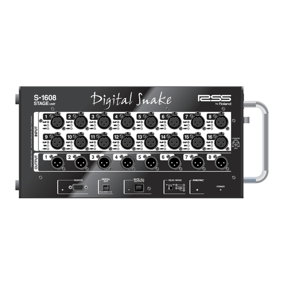
Page 17: 4-Panel Descriptions
Panel Descriptions S-1608 Stage Unit / S-0816 FOH Unit S-1608 Front Panel fig.4-01.eps S-0816 Front Panel fig.4-01.eps S-1608/S-0816 Digital Snake Owner’s Manual... - Page 18 If you’re using the S-4000 RCS on a computer, connect the computer’s RS-232C port to this connector. See Chapters 6 and 7 for information about remote control of the S-1608/S-0816 System. See Appendix B: Connector Information for a diagram of the REMOTE (RS-232C) connector.
- Page 19 4—Panel Descriptions 5—Digital Out Connector (Optical Type) This optical type digital out connector outputs the audio signal input to INPUT 1/2 of the S-1608/ S-0816. 6—[MUTE ALL OUTPUTS] Button The [MUTE ALL OUTPUTS] button is a momentary switch used to temporarily mute the S-1608/ S-0816 System’s audio outputs.
-
Page 20: S-1608/S-0816 Side Panel
Connect one end of the supplied AC power cord to a grounded AC outlet, and the other end to the POWER AC INPUT jack to provide power for the S-1608’s or S-0816’s internal power supply. Use the cord clamp on the side panel to prevent the power cord from being accidentally pulled out. - Page 21 4—Air Intake Vents 5—Cooling Fan Exhaust Vents The S-1608/S-0816 contains cooling fans that prevent the unit from overheating. The air intake vents provide fresh air for the cooling fans and the fans expel hot air through these vents. Be sure never to block the cooling fan exhaust vents and air intake vents. Doing so may cause the S-1608/S-0816 to overheat and be damaged.
-
Page 22: S-4000R Remote Controller
S-4000R Front Panel fig.4-05.eps 1—Signal Status Indicators These indicator lights show signal status for each of the S-1608/S-0816 System’s 24 input channels. • CLIP—lights red when the input signal exceeds 0 dB (after A/D conversion). Once a CLIP indicator lights, it stays lit until cleared with the [CLIP CLEAR / ENTER] button. - Page 23 Use this knob to set the preamp gain for the currently selected S-1608/S-0816 System’s input channel. Indicator lights surrounding the [GAIN] knob show the current gain setting. Each S-1608/S-0816 System’s input channel’s gain range is -45 to +10 dBu with the pad on, and -65 to -10 dBu with the pad off.
-
Page 24: S-4000R Rear Panel
This indicator lights when REAC communication is established within the S-1608/S-0816 System. If REAC communication fails, this indicator will flash. 12—CTRL Indicator The indicator lights when the S-4000R is connected to a powered-on S-1608 or S-0816 and communication is established S-4000R Rear Panel fig.4-06.eps... -
Page 25: 5-S-1608/S-0816 System Overview
S-1608/S-0816 System Overview Concept The S-1608/S-0816 System brings the digital revolution to the world of audio snakes. Using computer networking technology, the system allows you to transfer 24 channels of high-quality audio over an extremely long distance on a single lightweight cable. The digital advantage also brings with it easy installation, low cost, portability, and pain-free expansion. -
Page 26: Things To Know
40 channels of digital audio over a single Cat5e Ethernet cable. The S-1608/S-0816 system transfers a total of 24 channels of audio signal: 16 channels from the S- 1608 and 8 channels from the S-0816. -
Page 27: Ethernet Connectors
When using the S-4000-SP REAC splitter to extend the REAC cable or to split connect a separate S-1608 or S-0816 • When connecting the S-1608/S-0816 and S-4000S/S-4000H via REAC, see Page 66 for more information. Ethernet connection standards recommend using straight-through cables to connect devices to the ports on a switching hub, and crossover cables when connecting hub-to-hub. -
Page 28: About Ethernet Switching Hubs
Broadcast feed S-1608 (Master) S-0816 (Split) S-4000-SP or switching hub S-0816 (Split) Multitrack recorder S-0816 (Slave) S-0816 (Split) Monitor console Main console REAC device modes—including “Master,” “Slave,” and “Split”—are discussed starting on Page 38. S-1608/S-0816 Digital Snake Owner’s Manual... -
Page 29: A/D-D/A Conversion And Signal Optimization
S-4000R Remote Controller or a personal computer running the S-4000 Remote Control Software (S-4000 RCS). If RS-232C devices are connected to the REMOTE connectors on both the S-1608 and S-0816, the system can be controlled from either device (though only one remote device can control the system at any given time). -
Page 30: The System Components: A Closer Look
As it name suggests, the S-0816 FOH Unit’s main application is near the FOH mixing console. However, the S-0816 can be used anywhere you need to receive stage audio from the S-1608—at a monitor console, a multi-channel recording device, a broadcast feed, etc. Additionally, multiple S- 0816 units can be used for split destinations when connected to the system via an Ethernet switching hub. -
Page 31: S-4000R Remote Controller
5—S-1608/S-0816 System Overview S-4000R Remote Controller The S-4000R functions as a remote controller for the S-1608/S-0816 System. It can be connected to either the S-1608 or S-0816 unit, whichever is most convenient for you. • Input channel control—The S-4000R provides control over the S-1608/S-0816 System’s input channels. -
Page 32: 6-Using The S-1608/S-0816 System
Avoid using the S-1608 or S-0816 in sealed-type rack mounts. As this type of rack does not permit heated air within the rack to be expelled, the heated air is drawn into the S-1608 or S-0816 as a result, thus preventing adequately efficient cooling. -
Page 33: S-4000R
Use the following procedure to install the rack-mount brackets on the S-4000R. Disconnect the RS-232C cable from the S-4000R unit. Install the S-4000R rack-mount brackets with the supplied screws as shown in the following diagram. fig.6-08.eps S-1608/S-0816 Digital Snake Owner’s Manual... -
Page 34: Using The Ac Cord Clamp
6—Using the S-1608/S-0816 System Using the AC Cord Clamp The S-1608 and S-0816 units have AC cord clamps to prevent the cord from being pulled out accidentally. Remove only the screws shown in the following diagram (2 screws total), and detach the AC cord clamp. -
Page 35: Installing The Included Ferrite Core On Ethernet Cables
Installing the Included Ferrite Core on Ethernet Cables One ferrite core is included with both the S-1608 and S-0816 for installation on Ethernet cables. Install a ferrite core on REAC cable SC-W100S (sold separately) or Ethernet cable near the RJ45 plug that will be connected to a REAC port. -
Page 36: Using The Reac Connector Cover (S-1608 And S-0816)
Attaching the Rubber Feet Attach these as required, such as when you’re using the S-1608 or S-0816 without mounting it on a rack or the like. Peel off the double-sided tape from the rubber feet and affix the rubber feet at the locations shown in the following figure. -
Page 37: Connection Overview
To prevent malfunction and/or damage to speakers or other devices, always turn down the volume, and turn off the power on all devices before making any connections. fig.6-14.eps_90 S-1608 16x8 (Master REAC device) 8 outputs from console 16 mic/line inputs... -
Page 38: Setting The Reac Mode
6—Using the S-1608/S-0816 System Setting the REAC Mode fig.6-15.eps The S-1608 and S-0816 each feature a [REAC MODE] switch. This switch sets the REAC behavior of each device, and determines how audio is transferred throughout the system. Each unit’s [REAC MODE] switch must be set properly for correct system operation. -
Page 39: Setting The [Reac Mode] Switches
Setting the [REAC MODE] Switches fig.6-16.eps The [REAC MODE] switch on the S-1608/S-0816 is recessed from the front panel so that its setting can’t be changed inadvertently. To change the switch setting, use a blunt-tipped instrument such as a ball-point pen, mechanical pencil, etc. -
Page 40: Component Connections
On the S-1608: • Connect one end of the supplied AC power cord to a grounded AC outlet, and the other end to the POWER AC INPUT jack to provide power for the S-1608’s internal power supply. On the S-0816: •... -
Page 41: Reac Cable Length Extension
If the REAC cable is disconnected while [MUTE ALL OUTPUTS] is held, it’s possible that one of the S-1608 or S-0816 will remain in a muted state when [MUTE ALL OUTPUTS] is released. If this occurs, use the following procedure: Reconnect the REAC cable. -
Page 42: Notes About Handling Cat5E Cables (Reac Cables)
If you require a longer cable than the one provided, you can use an off-the-shelf RS-232C cable or fabricate your own. See Appendix B: Connector Information for an RS-232C pin out diagram. The S-4000R can be connected to either the S-1608 or S-0816. Connect it to whichever device location is most convenient for you. -
Page 43: Audio Connections
Note that [MUTE ALL OUTPUTS] only mutes the outputs of the S-1608/S-0816 System, and not the outputs of other devices. Before connecting the audio outputs on the S-1608 and S-0816 units to the audio inputs of other devices, always turn down the volume or turn off the power on the receiving devices to prevent possible damage. -
Page 44: S-1608/S-0816 Audio Inputs
6—Using the S-1608/S-0816 System S-1608/S-0816 Audio Inputs The S-1608’s (S-0816’s) audio inputs are used to send source audio signals to the S-0816’s (S-1608’s) audio outputs. Connect the output of balanced audio devices (microphones, instrument outputs, etc.) to the balanced audio inputs on the S-1608 (S-0816) front panel. -
Page 45: Input Status Indicators
(S- 1608/S-0816 Audio Inputs). When audio outputs from an S-1608 or an S-0816 are connected to inputs of external devices such as mixing consoles, please be sure to turn off the phantom power supply from these external devices. -
Page 46: Powering Up
Power is supplied to the S-1608/S-0816, and the POWER indicator lights up. The S-1608 and S-0816 units are equipped with protection circuits. A brief interval (a few seconds) after power up is required before the units will operate normally. -
Page 47: System Status Indicators
6—Using the S-1608/S-0816 System System Status Indicators The S-1608, S-0816, and S-4000R have system status indicators that allow you to monitor the integrity of the component connections when the system is powered up. Power Indicators S-1608/S-0816 fig.6-30.eps This indicator lights when the unit is receiving power from its internal power supply. -
Page 48: Muting The System Outputs
Indicator System’s audio outputs. On the S-1608 or S-0816 front panel, press and hold the [MUTE ALL OUTPUTS] button. After approximately 1.5 seconds, its indicator will light. No sound is output while the indicator is lit. When you have finished making input connections to the unit, release [MUTE ALL OUTPUTS]. -
Page 49: Using The S-4000R Remote Controller
See Chapter 7 for more about split setups. In the following sections, we’ll show you how to use the S-4000R’s functions. Before proceeding, make sure that the S-4000R is connected to the S-1608 or S-0816 as described on Page 42. Lock Mode fig.6-36.eps... -
Page 50: Monitoring Input Signals
Signal Status Indicators The S-4000R has two rows of signal status indicators that allow you to monitor the signal activity on the S-1608/S-0816 System’s 24 audio inputs (1–16 for the S-1608 and 17–24 for the S-0816). fig.6-37.eps S-1608 INPUT 1–16 S-0816 INPUT 1–8... -
Page 51: S-1608/S-0816 Input Channel Settings
6—Using the S-1608/S-0816 System S-1608/S-0816 Input Channel Settings With the S-4000R unlocked, use the following procedures to adjust settings on the S-1608 and S-0816 input channels. To retain your changes to the S-1608/S-0816 system’s input channel settings, lock the S-4000R before powering down the S-1608/S-0816 System. -
Page 52: Input Pad
While a channel’s input pad setting (on/off) is changed, its output is temporarily muted to avoid noise. Phantom Power Each of the S-1608/S-0816 system’s inputs can supply +48 V phantom power to devices that require it, such as condenser microphones or active direct boxes. -
Page 53: Stereo Link
6—Using the S-1608/S-0816 System Stereo Link The Stereo Link function allows you to link odd/even adjacent S-1608/S-0816 system’s input channel pairs (1/2, 3/4, etc.). When channels are linked, gain and pad settings made on one channel of the linked pair will be duplicated on the other. This can be convenient when audio devices with stereo outputs are connected to the S-1608 or S-0816. -
Page 54: Memory Function
The S-1608/S-0816 system features 10 user-storable memory presets. A memory preset contains channel settings (preamp gain, pad, phantom power, and stereo link) for all of the S-1608/S-0816 system’s 24 input channels. Using memory presets, you can quickly reconfigure the S-1608/S-0816 for frequently used audio input setups. -
Page 55: 7-Advanced Use
Using Two S-4000R Units in a Single S-1608/S-0816 System As discussed in Chapter 6, the S-4000R can be connected to either the S-1608 or S-0816. However, if you have a second S-4000R (available separately), you can connect one to each unit. This allows for control and signal monitoring of the S-1608/S-0816 System at the location of either unit. -
Page 56: Computer Control (S-4000 Rcs)
100 memory presets—Store and recall up to 100 different S-1608/S-0816 input setups. • Integrated monitoring and control of multiple systems—You can connect up to four S-1608/S-0816 Systems to multiple RS-232C ports on a personal computer. This allows for control and signal monitoring of multiple systems from a single interface. -
Page 57: What You'll Need
Cat5e cables, and you’re ready to go! Besides this setup convenience, REAC splits provide pristine audio quality—once the input signals are converted to digital data in the S-1608, they can be split as many times as you wish with absolutely no loss in quality. -
Page 58: Split Connection Overview
7—Advanced Use Split Connection Overview fig.7-02.eps_90 S-4000-SP or S-1608 16x8 (Master REAC device) Ethernet switching hub 8 outputs from console REAC cable SC-W100S or Cat5e cable S-0816 8x16 (Split REAC device) 16 mic/line inputs 16 mic/line sources from the stage... -
Page 59: Notes On Split Setups
See Page 38 for a discussion about the [REAC MODE] switches and how they affect REAC signal flow. With their power off, set the units as follows: On the S-1608, set the [REAC MODE] switch to M. On the primary S-0816 (usually at the FOH position), set the [REAC MODE] switch to S. -
Page 60: Reac Connections
7—Advanced Use REAC Connections For the REAC connections: • Using Cat5e cables, connect the REAC port on the S-1608/S-0816 units to ports on the REAC splitter S-4000-SP or the switching hub. fig.7-03.eps REAC Splitter S-4000-SP or Switching hub S-1608 S-0816... -
Page 61: Audio Connections And Power Up
Connect audio devices to the Master and Slave REAC devices’ inputs and outputs. Connect audio devices to the Split REAC devices’ outputs. S-1608 and S-0816 audio connections are explained in Chapter 6. Turn on any devices connected to the Master and Slave REAC devices’ audio inputs. -
Page 62: 8-Applications
Applications 16x8 System fig.8-01.eps_80 S-1608 16x8 (Master REAC device) 8 outputs from console 16 mic/line inputs REAC cable SC-W100S or Cat5e cable S-0816 8x16 (Slave REAC device) 16 mic/line sources from stage 8 outputs from console S-1608/S-0816 Digital Snake Owner’s Manual... -
Page 63: 16X8 System With 16 Channel Split
8—Applications 16x8 System with 16 Channel Split fig.8-02.eps_90 S-4000-SP or S-1608 16x8 (Master REAC device) Ethernet switching hub 8 outputs from console Cat5e cables S-0816 8x16 (Split REAC device) 16 mic/line inputs 16 mic/line sources from the stage Monitor Console... -
Page 64: 32X16 System
8—Applications 32x16 System fig.8-03.eps_90 (2) S-1608 16x8 (Master REAC device) 16 outputs from console 32 mic/line inputs (2) S-0816 8x16 (Slave REAC device) REAC cable SC-W100S or Cat5e cable 32 mic/line sources 16 outputs from console from stage S-1608/S-0816 Digital Snake Owner’s Manual... -
Page 65: 32X16 System With 32 Channel Split
8—Applications 32x16 System with 32 Channel Split fig.8-04.eps_70 (2) S-1608 16x8 (Master REAC device) S-4000-SP or 16 outputs Ethernet switching hub from console (2) S-0816 8x16 (Split REAC device) REAC cable SC-W100S 32 mic/line inputs or Cat5e cable 32 mic/line sources from the stage... -
Page 66: Connection To S-4000S/S-4000H
The S-4000S input/output module (SI-AD4, SI-AES4/SO-DA4, SO-AES4) is set up as shown below. You should not attach nor remove the module. Be sure to consult with the nearest Roland Service Center. Please visit www.rolandsystemsgroup.net for the latest information about the S-1608/S-0816 System. -
Page 67: Appendices
Appendices Appendix A: Troubleshooting The components in the S-1608/S-0816 System provide many different indicators that show the current system status. Additionally, the units provide error indicators that let you know whenever a potentially serious problem is detected in the system. -
Page 68: S-4000R Unit: System Status Indicators
CLIP 2 An exhaust fan on the Master • Turn off the power to prevent overheating and damage REAC unit has stopped working • Consult with the nearest Roland Service Center • None Flashing Recovery from the above error • Check REAC cabling... -
Page 69: Appendix B: Connector Information
Note: Pins 4, 5, 7, and 8 are not used in this application, but may be wired in the cable as shown. Cat5e Straight-Through Wiring fig.app-02.eps Note: Pins 4, 5, 7, and 8 are not used in this application, but may be wired in the cable as shown. S-1608/S-0816 Digital Snake Owner’s Manual... -
Page 70: Rs-232C (Remote) Connector (D-Sub, Db-9-Type)
Short to Pin 7 Note: Pins 1, 4 and 9 are not used in this application, but may be wired in the cable as shown. S-1608/S-0816 Audio Connectors (XLR-type) S-1608/S-0816 XLR Audio Pin Outs (INPUT and OUTPUT) Balanced connections (recommended): fig.app-05.eps... -
Page 71: Appendix C: Ethernet Switching Hub Requirements
When a switching hub is used in-line with REAC cables, the network latency will increase by the amount of processing delay introduced by the hub itself. The actual delay is dependant upon the specifications of the hub, though the maximum delay amount for a single hub should be about 200 microseconds. S-1608/S-0816 Digital Snake Owner’s Manual... -
Page 72: Appendix D: Specifications
200 microseconds. * 0 dBu = 0.775 V rms * In the interest of product improvement, the specifications and/or appearance of this unit accessories are subject to change without prior notice. S-1608/S-0816 Digital Snake Owner’s Manual... -
Page 73: Specifications: S-0816 Foh Unit
200 microseconds. * 0 dBu = 0.775 V rms * In the interest of product improvement, the specifications and/or appearance of this unit accessories are subject to change without prior notice. S-1608/S-0816 Digital Snake Owner’s Manual... -
Page 74: Specifications: S-4000R Remote Controller
GAIN Indicators (15 steps) Memory 10 memory presets Power Supply Supplied from connected device (S-1608 or S-0816, through the remote cable) Dimensions 215 (W) x 87 (D) x 54.6 (H) mm 8-1/2 (W) x 3-7/16 (D) x 2-3/16 (H) inches Weight 0.8 kg... -
Page 75: Appendix E: Dimensions
Appendices Appendix E: Dimensions Dimensions: S-1608 Note: Dimensions are shown in millimeters. fig.app-12.eps S-1608/S-0816 Digital Snake Owner’s Manual... -
Page 76: Dimensions: S-0816
Appendices Dimensions: S-0816 Note: Dimensions are shown in millimeters. fig.app-13.eps S-1608/S-0816 Digital Snake Owner’s Manual... -
Page 77: Dimensions: S-4000R
Appendices Dimensions: S-4000R Note: Dimensions are shown in millimeters. fig.app-14.eps 54.6 S-1608/S-0816 Digital Snake Owner’s Manual... -
Page 78: Index
INPUT connectors , 27, 69 RJ45 connectors , 70 wiring , 29 RS-232C , 23, 50 Input meter (S-4000R) , 70 wiring , 36 Rubber feet , 53 linking input channels , 49 locking the S-4000R S-1608/S-0816 Digital Snake Owner’s Manual... -
Page 79: Radio Frequency Interference Statement
Cet appareil numérique de la classe B respecte toutes les exigences du Règlement sur le matériel brouilleur du Canada. For the USA DECLARATION OF CONFORMITY Compliance Information Statement Model Name : S-1608 / S-0816 Type of Equipment : Stage Unit / FOH Unit Responsible Party : Roland Systems Group U.S. - Page 80 Information When you need repair service, call your nearest Roland Service Center or authorized Roland distributor in your country as shown below. FINLAND RUSSIA OCEANIA EUROPE ASIA Roland Scandinavia As, MuTek Filial Finland Dorozhnaya ul.3,korp.6 Roland Corporation AUSTRIA/BELGIUM/ 117 545 Moscow, RUSSIA...
Need help?
Do you have a question about the Digital Snake S-1608 and is the answer not in the manual?
Questions and answers