Table of Contents
Advertisement
Quick Links
INSTALLATION & COMMISSIONING GUIDE - OUTDOOR
Please Read This Guide
Congratulations on your purchase of an
ActronAir air conditioning unit. This unit has
been designed and manufactured with the
highest quality standard in mind.
Please read this guide thoroughly and keep it
near the unit for future reference.
This manual is a controlled document which contains confidential and proprietary information.
Distribution, modification, copying and/or reproduction are prohibited without written consent from ActronAir.
SPLIT DUCTED COMMERCIAL UNIT
SPLIT DUCTED MODELS
OUTDOOR UNIT
SCA290C
SCA300C
SCA330C
SCA340C
SCA400C
Copyright © 2017 Actron Engineering Pty. Ltd. All rights reserved.
Advertisement
Table of Contents

Subscribe to Our Youtube Channel
Related Manuals for actionair SCA290C


Summary of Contents for actionair SCA290C
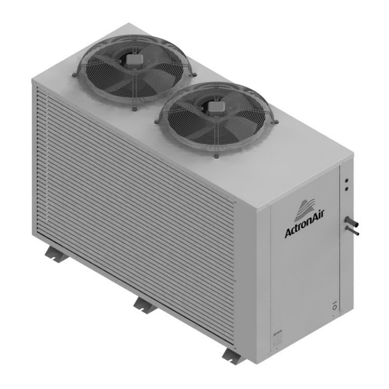
- Page 1 SPLIT DUCTED COMMERCIAL UNIT INSTALLATION & COMMISSIONING GUIDE - OUTDOOR SPLIT DUCTED MODELS OUTDOOR UNIT SCA290C SCA300C SCA330C SCA340C SCA400C Please Read This Guide Congratulations on your purchase of an ActronAir air conditioning unit. This unit has been designed and manufactured with the highest quality standard in mind.
-
Page 2: Table Of Contents
TABLE OF CONTENTS deliver the right amount of cooling or heating capacity that you demand. At extreme ambient conditions, the unit can still operate but will be at reduced capacity. General Information ............ Energy Efficient Refrigeration Circuits Safety Instructions ............The ActronAir refrigeration system was designed with the application of highly efficient capacity circuit that deliver Installation Information .......... -
Page 3: Safety Instructions
adequately supervised by a responsible person to for residential, office, schools and other air conditioning ensure that they can use the appliance safely. Young facilities applications, both for new construction or children should be supervised to ensure that they do retrofitting projects. -
Page 4: Installation Information
INSTALLATION INFORMATION Use only cleaning solvents that do not have ozone All service technicians handling refrigerant must be depletion factors. Properly dispose of used cleaning licensed to handle refrigerant gases. materials. Recover and Recycle Refrigerants INSTALLATION PREPARATION Never release refrigerant to the atmosphere! It is an offence in Australia to do so. -
Page 5: Components Overview
OUTDOOR UNIT COMPONENTS OVERVIEW OUTDOOR UNIT COMPONENTS OVERVIEW Outdoor Unit OD Fans Outdoor Unit Electrical Panel Reversing Valve LP Control Outdoor Coil HP Control Assembly Discharge Muffler Accumulator Compressor* *For illustration purpose only. Actual unit may vary. Unit shown above represent 1-Stage model. DESCRIPTION: ESS OTHERWISE SPECIFIED GENERAL TOLERANCES... -
Page 6: Unit Dimensions And Clearances
OUTDOOR UNIT DIMENSIONS / CLEARANCES OUTDOOR UNIT MODEL: SCA290C 1875 O/A OVERALL NOMINAL DIMENSION (H x W x D) = 1330 x 1875 x 875 USE M12 BOLT FOR FEET MOUNTING THIRD ANGLE NOTES: 1. All dimensions are in mm unless specified. - Page 7 INDOOR UNIT DIMENSIONS / CLEARANCES INDOOR UNIT MODEL: SCG290E OVERALL NOMINAL DIMENSION (H x W x D) 1530 O/A = 535 x 1530 x 770 SUPPLY DUCT (H x W) = 370 x 1065 1200 RETURN DUCT = 435 x 1200 DRAIN CONNECTION = 25mm ID GAS PIPES INDOOR COIL...
- Page 8 OUTDOOR UNIT DIMENSIONS / CLEARANCES OUTDOOR UNIT MODEL: SCA300C 1875 O/A OVERALL NOMINAL DIMENSION (H x W x D) = 1330 x 1875 x 875 USE M12 BOLT FOR FEET MOUNTING 1875 O/A COMP THIRD ANGLE NOTES: 1. All dimensions are in mm unless specified. PROJECTION 2.
- Page 9 INDOOR UNIT DIMENSIONS / CLEARANCES INDOOR UNIT MODEL: SCA300E OVERALL NOMINAL DIMENSION (H x W x D) = 535 x 1530 x 770 1530 O/A SUPPLY DUCT (H x W) = 370 x 1065 RETURN DUCT = 435 x 1200 1200 DRAIN CONNECTION = 25mm ID GAS PIPES...
- Page 10 OUTDOOR UNIT DIMENSIONS / CLEARANCES OUTDOOR UNIT MODEL: SCA330C 1875 O/A OVERALL NOMINAL DIMENSION (H x W x D) = 1330 x 1875 x 875 USE M12 BOLT FOR FEET MOUNTING THIRD ANGLE NOTES: 1. All dimensions are in mm unless specified. COMP PROJECTION 2.
- Page 11 INDOOR UNIT DIMENSIONS / CLEARANCES INDOOR UNIT MODEL: SCA330E OVERALL NOMINAL DIMENSION (H x W x D) 1735 O/A = 620 x 1735 x 770 SUPPLY DUCT (H x W) = 370 x 1065 1440 RETURN DUCT = 520 x 1440 1735 O/A DRAIN CONNECTION = 25mm ID GAS PIPE...
- Page 12 OUTDOOR UNIT DIMENSIONS / CLEARANCES OUTDOOR UNIT MODEL: SCA340C 1875 O/A OVERALL NOMINAL DIMENSION (H x W x D) = 1330 x 1875 x 875 USE M12 BOLT FOR FEET MOUNTING 1875 O/A COMP THIRD ANGLE NOTES: 1. All dimensions are in mm unless specified. PROJECTION 2.
- Page 13 INDOOR UNIT DIMENSIONS / CLEARANCES INDOOR UNIT MODEL: SCA340E OVERALL NOMINAL DIMENSION (H x W x D) 1735 O/A = 620 x 1735 x 770 SUPPLY DUCT (H x W) = 370 x 1065 1440 RETURN DUCT = 520 x 1440 1735 O/A DRAIN CONNECTION = 25mm ID 1440...
- Page 14 OUTDOOR UNIT DIMENSIONS / CLEARANCES OUTDOOR UNIT MODEL: SCA400C 1875 O/A OVERALL NOMINAL DIMENSION (H x W x D) = 1315 x 1875 x 875 USE M12 BOLT FOR FEET MOUNTING COMP THIRD ANGLE NOTES: 1. All dimensions are in mm unless specified. PROJECTION 2.
- Page 15 INDOOR UNIT DIMENSIONS / CLEARANCES INDOOR UNIT MODEL: SCG400E OVERALL NOMINAL DIMENSION (H x W x D) 1910 O/A = 680 x 1910 x 795 SUPPLY DUCT (H x W) = 370 x 1065 1595 RETURN DUCT = 575 x 1595 DRAIN CONNECTION = 20mm ID INDOOR COIL GAS PIPES...
-
Page 16: Unit Lifting Procedures
OUTDOOR UNIT LIFTING PROCEDURES A. CRANE LIFTING METHOD WARNING NOTE: Crane lifting method is recommended for high rise lifting. WH&S regulations must be observed and will take precedence during lifting process. Fig. 1 EQUIPMENT REQUIRED FOR CRANE LIFTING: Connect the loop ends of slings unto shackle - 1 x shackle - 2 x nylon slings... -
Page 17: Outdoor Unit Preparation
OUTDOOR UNIT PREPARATION 1. Remove mounting screws, as shown below: Outdoor Unit Access Panel Mounting Screws 2. Remove Access Panel. • Remove Access Panel-Electrical as illustrated below: • Disconnect Earth Cable as illustrated below: DESCRIPTION: REV. DRAWING NO. 0525-0XX Install Guide Commercial Split V1 - Page 21 - 1 MATERIAL: FINISH: ActronAir Pty Ltd... -
Page 18: Electrical Installation
ELECTRICAL INSTALLATION All electrical work must be carried out by a qualified accordance with local wiring rules. Wiring should conform technician. Make sure all wiring is in accordance with to all current electrical authority regulations and all wiring local wiring rules. Wiring connections should be made in connections to be as per electrical diagram provided with accordance with the wiring diagram provided. - Page 19 CIRCUIT BREAKER SIZE & CABLE SIZE REQUIREMENT Circuit Cable Size Breaker Size MAIN MODEL Amps O.D. to I.D. (4 Core + E) SCA290C / SCG290E 32.0 SCA300C / SCA300E 32.0 SCA330C / SCA330E 32.0 SCA340C / SCA340E 32.0 SCA400C / SCG400E 50.0...
-
Page 20: Cable Length And Specification
CONTROL CABLE LENGTH AND SPECIFICATION THIRD PARTY 230VAC ZONE BARRELS WITH CZ-1 ZONE KIT (1-Zone Up To 4-Zone Options / Max. of 4 Third Party Zone Motors per System) INDOOR UNIT R-410A “CAUTION” PLEASE ENSURE THERE IS NO GAS / PRESSURE IN THE FAN COIL UNIT BEFORE REMOVING COPPER END CAPS. -
Page 21: Field Pipe Connection
FIELD PIPE CONNECTION CAUTION The units described in this guide use R410A refrigerant, which operates at a pressure approximately 1.6 times higher than similar systems using R22. When installing equipment using R410A refrigerant, there are number of standards that must be met: •... - Page 22 E = Elbow Losses (See Table 1 on previous page) Equivalent Pipe Length = (H ) + (V ) + (E OUTDOOR UNIT TABLE 2: REFRIGERATION PIPING Outdoor Models Outdoor Model SCA290C SCA300C SCA330C SCA340C SCA400C Indoor Model SCG290E SCA300E SCA330E...
- Page 23 FIELD PIPE CONNECTION CAUTION Brazed joints should only be made while purging Nitrogen through the system. Failure to do so will cause carbon deposit to be left on the internal pipe surface, that in turn can cause system failure and void of warranty. Nitro Regulator Set to 2 L/s...
-
Page 24: Important Notes
FIELD PIPE CONNECTION See Diagram Below: Indoor Unit Nitrogen Hose Braze Joints Open Hose Detail - A IMPORTANT NOTES: Importance of Evacuation: • Any non-condensable product left in the system can cause the pressure in the high side of the system to increase and in turn, the compression temperature to rise. -
Page 25: Refrigerant Charging
The system of this unit operates with POE oil that rapidly absorbs moisture. The maximum time any system can be opened to atmosphere is 15 minutes. REFRIGERANT CHARGE DETAILS (R410A) Refrigerant Charge Pre-charged Length Additional Refrigerant Model (g/m) SCA290C 11,050 SCA300C 4725 per stage 50 per stage SCA330C 12,800 SCA340C... - Page 26 REFRIGERANT CHARGING SUB-COOLING AND SUPERHEAT CHARGING METHOD Parameters: LLT = Liquid Line Temperature SLT = Suction Line Temperature SCT = Saturated Condensing Temperature SST = Saturated Suction Temperature Cooling and Heating Operation: Adjust the refrigerant charge to obtain the correct super heat and sub-cool for optimal performance as follows: 1.
- Page 27 Allow the systems to stabilise (15-30 mins) and repeat the step 1-3 until superheat falls within the range specified in the table below: SUB-COOL / SUPER HEAT APPLICATION RANGE COOLING HEATING Model SUB-COOL SUPERHEAT SUB-COOL SUPERHEAT SCA290C SCA300C SCA330C 6 - 8 4 - 6 8 - 14 4 - 8 SCA340C SCA400C NOTE: The above sub-cool and superheat recommendations are based on the following rated conditions: °...
- Page 28 REFRIGERANT CHARGING R410A PRESSURE / TEMPERATURE CHART Pressure Pressure Pressure Pressure Temp Temp Temp Temp ° ° ° ° -34.4 194.9 805.9 2090.7 -30.7 206.9 834.1 2145.5 -26.8 219.2 862.9 2201.3 -22.8 231.9 892.6 2258.2 -18.6 245.1 922.8 2316.1 -14.2 258.7 953.8 2375.1...
-
Page 29: Maintenance
MAINTENANCE Maintenance Procedures To clean the refrigerant coils, use a soft brush and water This section describes the procedure that must be spray, such as garden hose or pressure washer with low performed as a part of normal maintenance program. pressure nozzle. -
Page 30: Maintenance Frequency Checklist
MAINTENANCE FREQUENCY CHECKLIST Electrical Service Period Parts Detail of Service Check Service Methods Printed Circuit Tighten Terminals as necessary on Visual Inspection Boards printed circuit boards Check all electrical Electrical terminals, mains, Re-tighten if loose. Connections communications, etc Magnetic Check for loose terminal Tighten electrical terminals. - Page 31 MAINTENANCE FREQUENCY CHECKLIST Outdoor Section Service Period Parts Detail of Service Check Service Methods For highly corrosive environment, Visual check for wash panels quarterly with water Casing / Panels damage, rust and dust & neutral detergent solution. Wax and Frames accumulation.
-
Page 32: Troubleshooting Guide
TROUBLE SHOOTING GUIDE Fault Possible Causes Remedies The system does not Built-in safety timers have been Ensure that 5 minutes has passed from turn on start. activated time. A breaker has turned OFF or a fuse Check breakers and fuses. has blown. - Page 33 TROUBLE SHOOTING GUIDE Fault Possible Causes Remedies Check the upper and lower temperature Set temperature cannot be The zone control set temperature limits are set correctly. See operation adjusted. limits are being exceeded. manual for details on setting upper and lower temperature limits.
-
Page 34: Status And Fault Codes
STATUS AND FAULT CODES CONTROLLER DISPLAY CODES OUTDOOR C7-4 Wall Controller FUNCTION / FAULT (Part C7) Cooling Mode Heating Mode - Normal Heating Mode - Compressor run time > 20 min Heating Mode - Defrost Heating Mode - Indoor Coil Pre-Heat Fault, Open Circuit Outdoor Coil Sensor Fault, Short Circuit Outdoor Coil Sensor Fault, High - Low Pressure... -
Page 35: Key Components List
KEY COMPONENTS LIST PART DESCRIPTION SCA290C SCA300C SCA330C SCA340C SCA400C NUMBER 1560-437 1560-440 Compressor 1560-438 1560-463 1560-459 2025-006 Crankcase Heater 2025-005 2505-106 Outdoor Fan 2505-134 2020-097 Outdoor Control Board 2020-045 2020-100 Stage 2 Control Board 2020-009 HP Switch 2060-019 LP Switch 2060-020 Metering Device - (0.0650”) Piston... -
Page 36: Key Parts List
KEY PARTS LIST PART DESCRIPTION SCG290E SCA300E SCA330E SCA340E SCG400E NUMBER 2520-329 Indoor Fan 2520-324 2520-327 Indoor Control Board - CPI 2020-101 ECM Filter 4080-013 Metering Device - (0.0820”) Piston 4540-082 Metering Device - (0.0846”) Piston 4540-084 Metering Device - (0.0880”) Piston 4540-088 Metering Device - (0.0906”) Piston 4540-090... -
Page 37: Startup And Commissioning Report
START UP & COMMISSIONING REPORT INSTALLATION INFORMATION Name: Tel. Number: CUSTOMER Address: Name: Tel. Number: INSTALLER Address: Site Address: Date Installed: Model: Serial Number: CIRCUIT TEMPERATURE SETTINGS & AMBIENT TEMPERATURE SYSTEM 1 SYSTEM 2 Supply Air Temperature °C Supply Air Temperature °C Return Air Temperature °C... - Page 38 THIS PAGE WAS INTENTIONALLY LEFT BLANK...
- Page 39 THIS PAGE WAS INTENTIONALLY LEFT BLANK...
- Page 40 1800 119 229 www.actronair.com.au Refrigerant Trading Authorisation No.: AU06394 Actron Engineering Pty Ltd ABN 34 002 767 240 Printed in Australia HEAD OFFICE SYDNEY AUSTRALIA Part No. 0525-056 Copyright © 2017 Actron Engineering Pty. Ltd. Rev. No. 3.0 180202...
Need help?
Do you have a question about the SCA290C and is the answer not in the manual?
Questions and answers