Table of Contents
Advertisement
Quick Links
R32
R410A
AUXB004HLAH
AUXB005HLAH
AUXB007HLAH
AUXB009HLAH
AUXB012HLAH
AUXB014HLAH
AUXB018HLAH
R32
AUXN009HLAH
AUXN012HLAH
AUXN014HLAH
R32/R410A
R32 or R410A.
Refer to the rating label for the serial number,
manufactured year and month.
INSTALLATION MANUAL
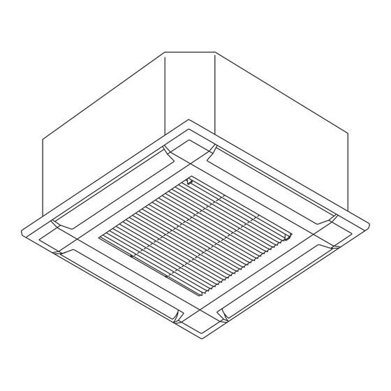
VRF system indoor unit (Cassette Type)
For authorized service personnel only.
INSTALLATIONSANLEITUNG
VRF-System Innengerät (Kassettentyp)
Nur für autorisiertes Fachpersonal.
MANUEL D'INSTALLATION
Unité intérieure à système VRF (type cassette)
Pour le personnel agréé uniquement.
MANUAL DE INSTALACIÓN
Unidad interior del sistema VRF (Tipo casete)
Únicamente para personal de servicio autorizado.
MANUALE DI INSTALLAZIONE
Unità interna del sistema VRF (tipo a cassetta)
A uso esclusivo del personale tecnico autorizzato.
ΕΓΧΕΙΡΙΔΙΟ ΕΓΚΑΤΑΣΤΑΣΗΣ
Εσωτερική μονάδα συστήματος VRF (Τύπος Κασέτας)
Μόνο για εξουσιοδοτημένο τεχνικό προσωπικό.
MANUAL DE INSTALAÇÃO
Unidade interior do sistema VRF (Tipo Cassete)
Apenas para técnicos autorizados.
MONTAJ KILAVUZU
VRF sistemi iç ünitesi (Kaset Tipi)
Yalnızca yetkili servis personeli için.
PART No. 9371022703-01
MADE IN P.R.C.
Advertisement
Table of Contents

Related Manuals for Fujitsu AUXN009HLAH


Summary of Contents for Fujitsu AUXN009HLAH
- Page 1 AUXB014HLAH A uso esclusivo del personale tecnico autorizzato. AUXB018HLAH ΕΓΧΕΙΡΙΔΙΟ ΕΓΚΑΤΑΣΤΑΣΗΣ Εσωτερική μονάδα συστήματος VRF (Τύπος Κασέτας) Μόνο για εξουσιοδοτημένο τεχνικό προσωπικό. AUXN009HLAH MANUAL DE INSTALAÇÃO AUXN012HLAH AUXN014HLAH Unidade interior do sistema VRF (Tipo Cassete) Apenas para técnicos autorizados. MONTAJ KILAVUZU VRF sistemi iç...
-
Page 2: Table Of Contents
INSTALLATION MANUAL [Original instructions] CAUTION PART No. 9371022703-01 Read carefully all security information before use or install the air conditioner. VRF system indoor unit (Cassette type) Do not attempt to install the air conditioner or a part of the air conditioner by yourself. Contents This unit must be installed by qualified personnel with a capacity certificate for handling refrigerant fluids. - Page 3 CAUTION CAUTION 1. General 3. Repairs to sealed components 1-1 Installation • During repairs to sealed components, all electrical supplies shall be disconnected from • That the installation of pipe-work shall be kept to a minimum. the equipment being worked upon prior to any removal of sealed covers, etc. •...
-
Page 4: About This Product
2. ABOUT THIS PRODUCT CAUTION 10. Decommissioning 2.1. Installation tools • Before carrying out this procedure, it is essential that the technician is completely familiar with the equipment and all its detail. • It is recommended good practice that all refrigerants are recovered safely. WARNING •... -
Page 5: Optional Parts
Name and Shape Q’ty Application CAUTION Drain hose For installing drain pipe Do not install the unit in the following areas: VP25 (O.D.32, I.D.25) • Area with high salt content, such as at the seaside. • It will deteriorate metal parts, causing the parts to fail or the unit to leak water. •... -
Page 6: Discharge Direction Setting
Nut (locally purchased) Washer A (accessory) 3.3. Discharge direction setting The insulation side should be facing downward. The discharge direction can be selected as shown below. 30 or more * Select the most appropriate airflow Fig. B Unit: mm Hook direction from 3 or 4 directions according 100 or more After installing the body,... -
Page 7: Flare Connection (Pipe Connection)
4.3. Flare connection (pipe connection) 4.4. Installing thermal insulation Install the thermal insulation after performing a refrigerant leak check (refer to the installa- WARNING tion manual for the outdoor unit for details). Coupler thermal insulation Tighten the flare nuts with a torque wrench using the specified tightening method. Oth- erwise, the flare nuts could break after a prolonged period, causing refrigerant to leak •... -
Page 8: Electrical Wiring
When lifting up drain: NOTE: Check for drainage Drain pipe • Height of inclined pipe should be less than 700 mm from the ceiling. A rise dimension Pour about 1 liter of water over this range will cause leakage. from the position shown in the •... -
Page 9: Electrical Requirement
AUXB018HLAH 0.50 A (2) Use the specified cables, connect them securely, and fasten them so that there is no AUXN009HLAH 0.40 A stress placed on the terminals. (3) Use an appropriate screwdriver to tighten the terminal screws. -
Page 10: Connection Of Wiring
(2) Connect the connection cable, with the cable tie. WARNING Use ring terminals and tighten the terminal screws to the specified torques, otherwise, Y1,Y2: Remote abnormal overheating may be produced and possibly cause heavy damage inside the controller cable unit. Cable tie (medium) (accessories) Tightening torque... -
Page 11: External Input And Output (Optional Parts)
NOTES: Mode Function setting Input signal Command • For details on options, refer to the each installation manual. OFF → ON Forced stop 46-02 • If using pulse input, an optional External input and output PCB or Expansion kit is ON →... -
Page 12: Remote Sensor (Optional Parts)
(2) Refrigerant system address 6.7. Remote sensor (Optional parts) Rotary switch (REF AD ×1)...Factory setting “0” Connection method Rotary switch (REF AD ×10)...Factory setting “0” • Remove the existing connector and replace it with the remote sensor connector (ensure In the case of multiple refrigerant systems, set REF AD SW as shown in the Table A for that the correct connector is used). - Page 13 7.3.1. Button name and function Setting Function Function number Details number (♦: Default) Adjust the vertical airflow direction. All 00 ♦ Standard Vertical airflow direction louvers are adjusted airflow direc- together. Raise tion (Cassette type only) (Prohibited) 00 ♦ — (Prohibited) 00 ♦...
-
Page 14: Cassette Grille Installation
(3) Attach the connector cover. 8. CASSETTE GRILLE INSTALLATION Connector cover Screw 8.1. Remove the intake grille (1) Slide the 2 grille hook 8.3. Attach the intake grille The installation is the reverse of “REMOVING THE INTAKE GRILLE”. The intake grille can be rotated and installed 4 ways to suit the user’s preference. Grille hook CAUTION The louver angle cannot be changed if the power is not on, (If moved by hand, it may be... -
Page 15: Error Codes
Wired remote controller display 11. ERROR CODES UTY-RNR*Z* (2-wire type) If you use a wired type remote controller, error codes will appear on the remote controller display. If you use a wireless remote controller, the lamp on the photodetector unit will Touch the [Next Page] (or [previous page]) Error icon output error codes by way of blinking patterns.
Need help?
Do you have a question about the AUXN009HLAH and is the answer not in the manual?
Questions and answers