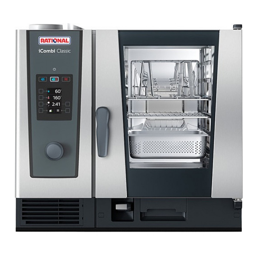
Rational iCombi, iCombi Classic - Food Equipment Manual
- Quick service reference (4 pages) ,
- Service & reference manual (3 pages) ,
- Original installation instructions (20 pages)
Advertisement
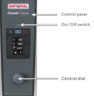
SERVICE REFERENCE iCombi
ADDITIONAL FUNCTIONS
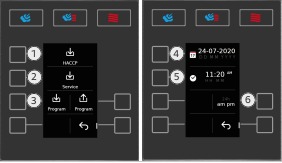
- HACCP download
- Service download
- Programme upload and download
- Date
- Time
- Adjust the display setting to the time
- Menu item: Information
- Draining the steam generator (ESG)
- Service level
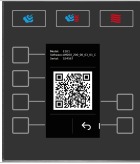
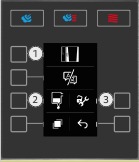
Information:
Model
Software
- Programmes:
- Cleaning
- Setting
- Set buzzer tone
- Buzzer volume
- Note on rinsing the hand shower
- Switch to another setting level
CALIBRATION/SELF-TEST
The calibration values are determined after installation during the selftest and during the calibration and stored on the SD card and the PCB. On-site calibration is necessary when replacing:
Pressure sensor P1, B4 thermocouple humidity, fan wheel, micro SD card and PCB together, use of different hinging racks, installation of new air baffle, installation of hoods or Combi-Duo, customer complaints with uneven cooking results, subsequent relocation.
A self-test is necessary for new installations.
Start conditions:
Cooking cabinet sensor B1, control sensor B2, humidity sensor B4: < 40°C. In order to achieve the best possible calibration values, a closed GN container should be inserted 20 mm deep with the open side down in the middle in front of each fan wheel.
After a successful self-test, a flue gas analysis must be carried out for gas units!
Calibration errors
Calibration errors either occur during the self-test or a manual calibration. The error number refers to the calibration step in which the error occurred.
The most common calibration errors are:
- Step 0 error start conditions:
- B1, B2 or B4 over 40°C
- Filling cleaner box with water taking too long, problem with solenoid valve block or control solenoid
- 20: Differential pressure sensor faulty, loose cables n 100: Fan motor speed detection faulty
- 200: Steam heating does not work, (check voltage, SSR, plug X20, gas supply, energy optimisation)
ERROR CODE
| Service | Check and replace if necessary |
| 2 | Energy optimization active (only with installed energy optimization PCB) |
| 10 | SC-automatic error SC pump, Combi water box, pump-off hose |
| 11 | CDS sensor reporting too many pulses Level electrode, CDS sensor flow rate, I/O PCB |
| 12 | CDS sensor not reporting any signals CDS sensor, I/O PCB, water connection |
| 14 | Level electrode detecting no water even though CDS is measuring pulses Level electrode, water conductivity |
| 16 | EEPROM structure was replaced with a more recent software than that on the PCB, update the unit with the latest software |
| 17.X | Unit data incorrect (internal fault only possible for internal purposes) Inform RATIONAL; use Recovery Software |
| 19.X | x= type of error -1= EEPROM missing or not recognised; -2 = internal storage error (battery may have been removed) |
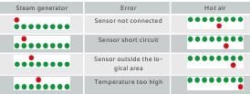
| 20.X | Thermocouple break, x= sensor: -1 Cooking cabinet B1; -2 Control sensor B2; -4= humidity B4; -8= Steam generator B5; -9: Thermocouple B9 faulty - only floor units |
| 23 | Temperature rise on the steam generator without request Steam heating check |
| 24 | Temperature rise in the cooking cabinet without request Hot air heating check |
| 25 | No water detection without cleaning Fan wheels do not run / no increase in performance at the fan motor when the water jet hits: Check water supply, pressure, hoses, CDS sensor, position of GN conductors and mobile oven racks |
| 28.x | Thermocouple, x= Sensor: -1: SG B5 too hot (>170°C); -2: Cooking cabinet B1 too hot (>350°C); -4: Steam generator B5 too cold (<2°C, heating possible again from 4°C) |
| 29.x | PCB temperature too high: -1: motor down; -2: motor centre; -4: Pump PCB; -16: I/O PCB -64: CPU PCB |
| 30 | Humidity measurement not working correctly Pressure sensor P1, connection hoses, measuring connection pieces, humidity sensor B4 |
| 31.xx | Thermocouple core temperature B3; x = error type: -1: core probe error; -11: external core probe error |
| 32.x | Fault in combustion system or gas supply, x= fault, y= combustion system -1.y (22= HA top, 32= steam, 42= HA bottom): 5x unsuccessful ignition process -2.y (17/18/49= HA top, 27/28/52= steam, 37/38/55= HA bottom): Flame current measured with gas valve closed -3.y (19= HA top, 29= steam, 39= HA bottom): Burner goes out 5 times during the burning phase -4.y (20= HA top, 30= steam, 40= HA bottom): The speed of the gas blower deviates from the target speed by more than 150 rpm |
| 33.x | Error in the control of the combustion system, x= error -1: Ignition box fault accumulation -2: Desired gas speeds breach condition >0 rpm or Min. < Start < Max. -3: Mains frequency outside 40...70 Hz -4: Phase and neutral conductor mixed up -5: Automatic ignition controller error |
| 34.xx | Bus signal missing:-1 motor top; -2 motor centre; -4 motor bottom (floor units only); -8 Pump PCB; -16 I/O power supply; -32 ignition box; |
| 35 | UltraVent: Bus signal / internal communication |
| 35.x | UltraVent error: -1 voltage missing; -2 Filter detection faulty (UV Plus only); -3 Thermocouple control error; -4 Thermocouple motor protection error; -5/6 Dirt in filter (pre-warning/immediate replacement); -7 Filter not inserted/no differential pressure measured |
| 36 | Differential pressure sensor fault (no signal output of 0.5V; check 12V at P1); P1 must be installed horizontally |
| 37 | Climate control malfunction: Check connecting hoses |
| 40 | Check the care pump (M18) in the function test (note: Y4 is activated at the same time, run the rinse programme) |
| 42.x | Solenoid valve x does not open: -1: fill Y1; -2: control Y2; -4 Care Y4; -5 Climate Y5/Y15 |
| 43.x | Solenoid valve x does not close: -1: Fill Y1; -2: control Y2; -4 Care Y4; -5 Climate Y5/Y15 |
| 44 | Steam heating faulty or inadequate during cleaning |
| 46.x | SC pump (M4); x= type of error: -1: defective; -2: Output too low |
| 47 | Wastewater pump (M15); -1: defective; -2: Output too low |
| 48 | Circulation pump (M17); -1: defective; -2: Output too low |
| 49 | Care pump (M18); x= type of error: -1: defective; -2: Output too low |
| 50 | Real time clock (date and time) not initialised |
| 51 | Check battery, replace if necessary |
| 52 | LED cooking cabinet light faulty |
| 63 | Water detected after dry calibration, repeat self-test with water |
| 64 | Unit calibrated dry – attempt to start humid cooking mode |
| 70 | Cooling fan error |
| 71.X | Power supply fault -1: General failure; -2: Undervoltage (<170V) |
| 72 | eSTB for HA or steam: Blink code on eSTB – error code, see description below |
| 73.x | Fault due to overtemperature on: -1 Motor top; -2 Motor bottom; -4 Motor centre; -8 Pump PCB; -16 Ignition box; -32 I/O power supply |
| 75.x | Internal bus interface: -1: Additional PCB energy optimization not detected; -2: Additional PCB 4-way relay is not detected, -4 (USA ONLY) voltage switching PCB is not detected |
| 76.xx | USA units ONLY Error voltage switching PCB -1: Voltage too low; -2: Internal check failed; -3 incorrect voltage setting 4 to -7: Internal error |
| 90 | Unit not yet calibrated, carry out calibration |
| 110 | SC pump faulty while care solution is in the steam generator (Remove error and set to released under Basic settings "Cleaning unlock") |
| 120 | Level electrode without signal while care solution is in the steam generator (Remove error and set to released under Basic settings "Cleaning unlock") |
| 121 | Additional function when operating the unit without water: Note on filling water into the control box |
| 140 | Permanent fault in the gas supply or in the hot air gas combustion system; -4 Pre-warning for cooking operation block; -8 Cooking operation block |
| 200 | Automatic motor positioning failed (mostly followed by error 201) |
| 201 | Carry out motor positioning |
| 900.xx | -8: Initialise date and time failed; -16: Battery empty or removed; -32: Data loss due to battery voltage; -48: Battery removed, unit data and clock initialisation incorrect (summary of errors -16 and -32); -64: System not able to write calibration data to memory; -512: Read error internal data due to timeout |
| 1000 | Water low; Check water supply |
| 1016 | USB stick is already described |
| 1017 | USB stick faulty |
| 1018 | Error writing recovery file |
| 1022 | no water during the switch-on routine (via CDS measurement) |
| 1024 | Programme termination due to a faulty core probe |
| 1025 | Programme up- and download faulty due to error in EEP- ROM |
| 1026 | Programme upload not possible due to incorrect programme creation |
| 1028 | Data from outside Connected Cooking cannot be processed. |
| 1029 | Incorrect gas blower speed |
| 1033.x | System Healthy x faulty: -1: incompatible software I/O PCB; -2: Unknown software I/O PCB; -3: Check BUS system From software 5.0.X: Pressing button "1" (see previous page) shows the relevant bus node |
| 2000.x | Software update error: -1: Time out exceeded; -2-3: Max. update time exceeded; -4: Unit in diagnosis or self test; -5: Update attempt during cooking; -6: Update attempt during shutdown routine; -7: Update attempt in show mode |
ERROR CODES REMOVED FROM SOFTWARE VERSION 5.0X
| Service | Check and replace if necessary |
| 1001 | Gas reset, check gas supply |
| 1002 | Check the power supply and polarity |
| 1003 | There is a lack of water for > 15 minutes |
| 1010 | Check the air filter |
| 1011 | Check the battery |
| 1012 | Carry out humidity calibration |
| 1018 | Error UltraVent hoods |
| 1020 | Motor error |
| 1021.x | Energy optimisation module faulty: -1-2: 4-way relay faulty; 3: USA voltage incorrect |
| 1024 | Termination due to a faulty core probe |
SOFTWARE UPDATE
- Switch on the unit.
- Connect the USB stick with the latest software to the USB interface.
- Software update starts automatically.
- Switch the unit off after a successful software update.
- Remove the USB stick.
![]()

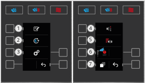
SERVICE LEVEL ACCESS (DIAGNOSIS, SETTINGS, RUNTIMES)
- Press the keys in the stated order.
![]()
- Enter the password "TECLEVEL" in the entry window.
- Confirm by clicking on the green tick. The diagnostic programme opens.
I/O PCB A10: DIAGNOSTIC LED
Red diagnostic LED on the rear side A10:
| Code 1 | 1x flash | Input voltage error |
| Code 2 | 2x flashes | Communication error A10 processor |
| Code 3 | 3x flashes | Fault on/off processor |
| Code 4 | 4x flashes | Input voltage too high |
| Code 5 | 5x flashes | Input voltage too low |
| Code 6 | 6x flashes | Mains frequency outside the tolerance |
| Code 7 | 7x flashes | Self-test A10 failed |
3 green diagnostic LED on the front side A10: see training manual
eSTB A15/A16: DIAGNOSTIC LED (3 LEDS A, B, C)
The green LED B flashes 16 times:
| Flashing with 2 of 16 signals | Input voltage short circuit |
| Flashing with 13 of 16 signals | Mains frequency not in the target range 45 – 65 Hz |
| Flashing with 14 of 16 signals | Input voltage below expected level of 140 V |
| Flashing with 15 of 16 signals | Input voltage above the expected level of 278 V |
| Flashing with 16 of 16 signals | The reset button was pressed too long during normal eSTL operation > Attempt reset again |
| Flashing with 3 – 12 of signals | Internal eSTL error > Replace eSTL info: a reset is recommended., |
Further details: See training manual
After solving the problem: Reset eSTL, press the reset button for three seconds.
Blink codes flash more than 8 times: This is most often due to the power supply to the unit (e.g. connection to generator)
Documents / ResourcesDownload manual
Here you can download full pdf version of manual, it may contain additional safety instructions, warranty information, FCC rules, etc.
Download Rational iCombi, iCombi Classic - Food Equipment Manual
Advertisement


Need help?
Do you have a question about the iCombi and is the answer not in the manual?
Questions and answers