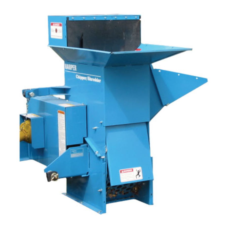
Harper 5400 - Chipper/Shredder Manual
- Operator's manual (38 pages) ,
- Operator's manual (44 pages)
Advertisement
To the Owner or Operator
As with all Harper products, the Chipper/Shredder has been developed through tough design and testing procedures to produce a top quality machine. This manual gives assembly, operating, and service information for the model 5400. Please read and understand all instructional material included with the Chipper/Shredder or its components before assembling and operating the equipment.
A Chipper/Shredder can present hazards to an operator who follows unsafe procedures in either the operation or maintenance of the unit. Therefore, SAFETY WARNINGS are presented at certain locations in the text.
THIS SYMBOL:
 SAFETY WARNING!
MEANING: Failure to understand and obey this warning may result in injury to you or others. Whenever this symbol is used, please pay very close attention to the information presented, and make sure you fully understand. If you do not, contact your dealer or Harper Industries, Inc. for clarification.
SAFETY WARNING!
ALL SHIELDS AND GUARDS MUST BE IN PLACE FOR PROPER AND SAFE OPERATION OF THIS EQUIPMENT. WHERE THEY ARE SHOWN REMOVED IN THIS MANUAL, IT IS FOR PURPOSES OF ILLUSTRATION AND INSTRUCTION ONLY. DO NOT OPERATE THIS EQUIPMENT UNLESS ALL SHIELDS AND GUARDS ARE IN PLACE.
Harper Industries, Inc. is continually striving to improve the design and performance of its products. We reserve the right to make changes in specifications and design without thereby incurring any obligation relative to previously manufactured products.
Specifications
| Hopper Size | 34" x 21" |
| Chipper Plate | ¾ thick machined and balanced steel plate |
| Chipper Knives | 4 knives machined from tool steel |
| Chipper Chute | 33"L x 13"W x 12"H |
| Chipper Capacity | 5" maximum diameter material |
| Rotor | 18" diameter with 36 free-swinging shredder knives |
| Shredder Capacity | 1" to 1 ¼" maximum diameter material recommended |
| Grate | 1 ½" grate is standard, ½" and ¾" are optional |
| Paint Finish | Durable polyester baked paint finish with epoxy primer The paint finish is extremely strong, and resists chipping and cracking. |
| Power | PTO Powered Model - 540 RPM from 18 to 30 HP tractor* * Warranty may be void if used on tractors over 30 HP. |
| Approximate Shipping Weight | PTO-600 lb. |
Torque Chart
| Size | In. - Lb. | F-t. - Lb. | N - m |
| No. 10-24 | 25-35 | 5-7 | 2.8-4.0 |
| 1/4 in. | 60-80 | 18-20 | 7-9 |
| 5/16 in. | 120-140 | 28-30 | 14-16 |
| 3/8 in. | 340-360 | 64-74 | 24-27 |
| 1/2 in | 126-150 | 90-100 |
NOTE: When tightening two or more screws on the same part, DO NOT tighten screws completely right away, or one at a time. To avoid distortion, first tighten all screws in sequence to one-third of torque value, then tighten to two-thirds of torque value, then tighten to full value.
General Safety Guidelines
SAFETY WARNING!
Failure to understand and obey these Safety Guidelines may result in injury to you or others.
Before Operation
- Check feed housings for children, pets and foreign objects before operating.
- Check to ensure that all belt guides are in place to prevent belts from slip- ping off the pulleys and systems from being accidentally engaged.
During Operation
- Wear approved eye and ear protection while operating the Chipper/Shredder.
- Keep all guards in place during opera- tion.
- Never operate the Chipper/Shredder with safety shields removed.
- Never allow hands, clothing or any part of the body to enter the discharge chute, feed chamber or near any moving parts.
- When placing material into the ma- chine, make certain there are no fore- ign objects such as rocks, cans, bot- tles or other hard materials included.
- Keep processed material from building up in the discharge area, as this may prohibit proper discharge and cause a back-feed of material through the feed opening.
- Keep all safety shields and guards in place and in good working condition.
- Keep your face and all body parts away from feed openings.
- Stay away from the discharge area when machine is in operation.
- Always keep proper balance and foot- ing, never overreach.
- If a foreign object should strike the cutting mechanism of the machine and cause an unusual noise or vibration, shut the PTO engine off immediately and allow it to come to a complete stop. Disconnect the PTO from the power unit, and then do the following:
- Inspect for damage.
- Repair or replace any damaged parts.
- Check for and tighten any loose bolts, nuts, fasteners or parts.
- Never attempt to move or transport Chipper/Shredder while engine or rotor is still operating.
- If the Chipper/Shredder should be come clogged, shut off the PTO and allow it to come to a complete stop. Disconnect the PTO shaft before clearing debris.
During Service
- Replace locknuts and locking screws if they can be tightened without feeling resistance for several turns before they are completely tight. Replace them with factory-authorized parts or their equivalent.
- If hardware is not secure, or if some of the hardware is over-tightened, equipment failure may result, posing possible safety hazards.
- Use genuine factory parts or parts with equivalent characteristics, including type, strength and material. Failure to do so may result in product malfunc- tion and possible injury to the operator or others.
- To prevent possible eye injury, always wear SAFETY GLASSES while servic- ing the equipment
Guards & Shields
- Keep the equipment and attachments in good operating condition.
- Keep all safety devices in place.
- Replace all worn, damaged, unusable, missing or lost safety shields and guards before operating the equip- ment.
Safety Decals
- If safety related or instructional decals become illegible or are removed, re- place them immediately.
- If you replace parts that have decals attached to them, make sure the decals are replaced with current ver- sions, and that decals are on the re- placement parts before the machine is operated again.
- New decals may be obtained from your local Harper Dealer.
Specific Safety Guidelines
CS-5400 PTO Powered Model
- Never operate the PTO unit when trac- tor is moving. Machine should only be operating when setting level on ground surface.
- To move the unit, shut the PTO off. Lift the 3-point hitch, and then move to the desired location.
- Keep hands, feet and clothing away from PTO driven parts.
- Keep all guards and shields in place during operation. Disengage PTO and shut off the engine before removing guards or shields.
- Never attempt to adjust, clean or lubri- cate the machine while it is in opera- tion.
- Operator should never wear loose clothing when working around PTO.
- Before starting tractor, make sure that the transmission and PTO are disen- gaged.
- A belt between the PTO shaft and the rotor shaft drives the cutting blades whenever the PTO shaft is turning.
SAFETY WARNING!
Recommended tractor PTO horsepower is 18 to 30 HP. Use of tractors above 30 HP may cause belt damage and will void warranty.
SAFETY WARNING!
Cutting blade rotation cannot be controlled from the Chipper/Shredder.
Control Identification
CS-5400 PTO Powered Model

PTO Shaft - Transfers power from the tractor to the Chipper/Shredder. Due to varia- tions in tractor styles, the operator is responsible for ensuring that the PTO shaft is the correct length for a given tractor. (See the Assembly instructions.)
3-Point Hitch Pins - Mounts the Chipper/ Shredder to the 3-Point Hitch of the tractor.
Chipper Chute - Materials to be chipped are fed into the chipper chute.
Shredder Hopper - Materials to be shredded are fed into the shredder hopper.
Jackshaft – The jackshaft is connected to the PTO shaft and used to adjust ten- sion for drive belts.
Discharge - The area where chipped and shredded materials are discharged.
SAFETY WARNING!
Make sure that angle of PTO shaft does not exceed 15 degrees.
Assembly
CS-5400 PTO Powered Model
- Mount feet onto machine base.
- Connect PTO shaft to input shaft of machine, tighten set screws on shaft.
- Mount 3-point hitch pins onto Chipper/Shredder.
- Mount Chipper/Shredder to 3-point hitch of tractor and secure with lynch pins.
![]()
Do not connect the PTO shaft at this time. - Raise the unit to the height where the PTO shaft would be level if installed (PTO shaft should be at shortest length).
- Hold the PTO shaft alongside the 540 yoke on the tractor and allow for ¾" clearance between the outer shield and the bell housing at the Chipper/Shredder end of the PTO shaft.
- If the PTO shaft is too long, separate the halves and cut the full amount of excess length from both the male and female half.
Note: If only one end is cut from the PTO shaft, the other end will bottom out during operation. Cut the inner and outer shields to compensate for the length adjustment.

- Connect the PTO shaft to the 540 yoke on the tractor to begin operation.


SAFETY WARNING!
- Keep pants and loose clothing away from PTO shaft and all other shafts, pulleys and belts.
- Never operate the Chipper/Shredder be-yond the suggested 540 PTO speed.
- Do not attempt to service machine while it is in operation.
Blower Attachment
- Remove blower and directional spout from boxes.
- Remove rear shaft guard and safety door from Chipper/Shredder.
- Mount blower attachment to Chipper/ Shredder using safety door hinge pin, secure blower to unit using 4 - 5/16" x 3/4" bolts and 5/16" nylock nuts.
- Install belt shield mount tab on top bolt of bearing using 1/2" lock nut.

- Mount drive pulley on drum shaft. Align pulleys and tighten to 17 ft-lb. Mount belt on unit routing idler in center of belt. Install belt shield using 5/16" bolts and flat washers.
- Mount lower directional spout to blower using 5/16" bolts and flat washers.
- Mount upper directional spout to lower using 5/16" x 3/4" bolts, 5/16" lock nuts and bearings. Make sure that 1/4" washer is placed between bearing and mount tab.
- Mount crank assembly to mount tab using 2 3/8" x 1" carriage bolts and 3/8" nylock nuts. Place 2 3/8" flat washers under each bolt location to shim up crank assy.
NOTE: This may vary due to required clearance for crank. - Mount deflector spout to upper spout using 2 5/16" x 34" truss head bolts. A 5/16" washer is used for a spacer between deflector and spout.

Discharge Grates
- The factory-installed standard discharge grate has 1½" diameter holes.
![]()
- Installing a discharge grate with small- er diameter holes can increase fine- ness of the shredded material.
- Discharge grates with ½" and ¾" diam- eter holes are available for the Chip per/Shredder.
- A discharge grate with parallel bars is available for shredding leaves or green material.

To change discharge grates:
- Remove the rear door hinge pin and remove the rear safety door.
- Remove the 6- 3/8" x 1" bolts holding the grate in place. Remove the grate.
![]()
- Install new grate. Make sure to install the rounded edge of the grate to the bottom.
- Reinstall bolts and rear safety door.

SAFETY WARNING!
- The cutting rotor is heavy and will continue to turn even though the operator has shut off the power source. Do not attempt to service or inspect the machine until you see that the shafts have stopped turning and that there is no noise coming from the machine.
- Never operate Chipper/Shredder without ALL GUARDS in place.
Operation
SAFETY WARNING!
- Obtain and wear safety glasses when operating this machine. Do not wear loose fitting clothing. Operator should always wear heavy- duty gloves, boots, and other ar- ticles of clothing.
- A safe operator is one who prac- tices safety and uses good common sense to protect him or herself from sharp objects and branches.
- Move the Chipper/Shredder to a clear level area outdoors before operating.
Do not operate on uneven, paved or other hard surfaced areas. Do not operate in the vicinity of bystanders. - To avoid personal injury, always keep face and body parts away from feed openings. Never over-reach and keep proper footing and balance.
CS-5400 PTO Powered Model
- Obtain and wear safety goggles before operating the Chipper/Shredder.
- Check feed housings for children, pets and foreign objects before operating.
- Mount PTO Chipper/Shredder to 3-point of tractor and connect PTO shaft to tractor output shaft.
- Adjust center link on tractor so that the Chipper/Shredder is setting level at the ground surface.
- Move the Chipper/Shredder to a clear level area outdoors before operating. Do not operate on uneven, paved or other hard surfaced areas. Do not operate in the vicinity of bystanders.
- Engage tractor PTO to begin operation.
SAFETY WARNING!
Do not exceed 30 MPH when towing the unit. Travel at speeds that are appropriate for conditions and always use safety chains.
Chipping
- Select limbs that are up to 5 inches in diameter; trim branches that will not fit into the chipper chute. Smaller branches can be bunched and ran through together.
- Place limb, butt end first, into the chipper chute until it touches the chipper knives.
The feed rate of the limb into the chip- per depends on the material and sharpness of the chipper knives. The operator can feed the limb by alternately inserting and retracting the limb or continuously feeding it, so long as it doesn't kill the engine or the trac- tor. By rotating the limb you can im- prove the cutting action of the chipper. - The chipping knives will become dull at varying times depending on the wood material used. Periodic sharpen- ing of knives will be required. Refer to the Service & Maintenance section for sharpening instructions.
Shredding
- Feed material such as grass, leaves, garden refuse, and branches up to 1" in diameter and 36" long into the shredder hopper.
- Use a leaf tamper, branch or similar object to push light material into shred- ding chamber.
- Feed material at an even pace to avoid plugging or lugging of the Chipper/Shredder. If the shredder should become plugged, refer to the service section of the manual before clearing plugged material. Branches or material that cause plugging or slow opera - tion should be fed at a slower pace to avoid plugging.
SAFETY WARNING!
- Never leave the machine unattend- ed, or attempt service or inspec- tion unless the machine has come to a complete stop, the engine has been shut off, and the spark plug has been disconnected.
- On PTO units, make sure the PTO and the tractor engine has been shut off and the machine has come to a complete stop.
NOTE: To avoid entanglement with material going into the shredder hopper it is suggested to use a throwing motion when feeding material.
Stopping Operation
CS-5400 PTO
- Move throttle on tractor to the slow position and disengage the PTO lever on the tractor.
- Shut off the tractor engine and allow the machine to come to a complete stop.
- If it is necessary to inspect or work on the Chipper/Shredder, always disengage the PTO and shut off the tractor engine before doing so.
Adjustments
SAFETY WARNING!
- The cutting rotor is heavy and will continue to turn even though the operator has shut off the power source. Do not attempt to service or inspect the machine until you see that the shafts have stopped turn- ing and that there is no noise com- ing from the machine.
- If the operator wants to slow the machine faster, he can do so by inserting a limb into the chipper chute so that it contacts the knives and slows the machine down.
- Never operate Chipper/Shredder without ALL GUARDS in place.
Belt Tension
- On initial operation of the Chipper/ Shredder, the belts may shrink and need readjustment after the first hour of use.
- Check the condition of drive belts be- fore each use or after every 25 hours of operation.
- Use only industrial V-belts. Do not use automotive belts.
- Do not over tighten belts. Excessive tension can cause premature bearing and belt failure.
- Use a straightedge to check alignment across the faces of pulleys after ad- justing belt tension to ensure that the belts will run true.
Belt Adjustment
CS-5400 PTO Powered Model
- Make certain that PTO shaft is removed from power source and un-mounted from 3-point hitch of tractor.

- Disconnect PTO shaft from Chipper/ Shredder and remove belt guards.

- Loosen bolts that mount the jackshaft pillow block bearings and move the shaft towards the frame.
- Remove the belt. Inspect or replace with a new belt.
- Move shaft away from frame to tighten belt and check to see that there is no more than 1/4" up and down play in the belt.
- Snug two bolts and check pulley alignment with a straightedge. If not aligned, loosen one bolt and adjust. Tighten all bolts on bearings when alignment is achieved.


Service & Maintenance
SAFETY WARNING!
- Before servicing or inspecting the Chipper/Shredder, make sure the power source is shut off and all moving parts have stopped.
- Disconnect the spark plug wire from the spark plug on Gas Pow- ered units.
On PTO Powered units, disconnect the PTO shaft from the tractor. - Always wear safety glasses and protective gloves when servicing the Chipper/Shredder.
Break-In Service
- After the first hour of use:
- Check belts. Re-tension if needed.
- Tighten set screws on bearings.
- Check nuts, bolts and fasteners to see that they are secure.
Lubrication
- Lubricate grease fittings after every 50 hours of use.
- There are 2 fittings on the rotor shaft of both the Gas and PTO Powered models.
- The PTO Powered model also has 2 fittings on the jackshaft and 2 fittings on the PTO shaft.
SAFETY WARNING!
- Wear protective gloves whenever handling or working near knives.
- Knives and their retaining hardware rotate at high speed. It is essential that they be mounted as described in the instructions to prevent accidents from flying metal.
Chipper Knives
Depending on the type of wood being fed into the chipper, the knives eventually become dulled, slowing chipping time and making it harder to produce chips. It is recommended that chipper knives be sharpened every 5 to 10 hours of use.
Removal:
- Remove the nine 5/16" bolts that fasten the top and bottom housings together.
- Remove the bolts that fasten the top of the grate and open hinged housing to access drum housing.
- Rotate drum so that knife is most acces sible through chipper chute. Remove the two 5/16" bolts and the chip per knife. Repeat this step for the remain ing knives.
Sharpening:
- The chipper blades can be sharpened with a bench grinder or done by a Harper dealership.
- Avoid getting blade surface too hot to where it changes color. This will re move the heat-treatment and may at- tribute to premature failure. When grinding, use short grinding intervals and cool in between with water.
- Remove equal amounts to keep knives balanced. Regrind knife-edge to 35 degrees of angle. Failure to do so may affect chipping performance.
Mounting:
- Mount chipper knives to rotor plate with sharpened edge facing chipper chute. Use Grade 5 5/16" x 1" bolts that have been treated with Loctite® or equivalent.
- After knives are mounted, tighten bolts to specified torque using the Standard Torque Chart.
- Re-assemble housing.
Setting Clearance:
- Remove safety shields covering the drive pulley on the rotor shaft front.
- Remove safety cover on rotor shaft rear side.
- Loosen screws on the rotor shaft pulley.
- Loosen set screws on front and rear rotor bearing lock collars.
- Using a hammer and punch, tap the lock collars opposite the direction of normal rotation and remove.
- Tap the end of the rotor shaft until the necessary 1/16 to 1/8 clearance between the knife and chipping block is obtained.
- After clearance is set, replace lock collars onto eccentric hub on bearings.
- Rotate the lock collars in the direction of the shaft rotation and set them with a hammer and punch.
- Using a straight edge, align rotor pulley with the drive pulley and tighten to 17 FT LBS. Set bushing with a punch and re torque.
- Inspect and make sure all parts are aligned and tight.
- Close top half of drum housing, install bolts and tighten. Replace grate pin in top of grate assembly.
- Make certain all bolts and fasteners are tight and secure before replacing shields and guards.
Shredder Knives
NOTE: The serrated shredder knives can be rotated four times and re-sharpened.
Removal:
- Remove the nine 5/16" bolts that fasten the top and bottom housings together.
- Remove the pin that fastens the top of the grate and open hinged housing to access drum housing.
- Remove the #10-24 bolt and nut from the knife shaft. Work with one shaft at a time only; this will eliminate any confusion as to proper spacing and alignment.
- Remove the knife shaft, knives and spacers, and reverse or replace desired shredder knives.
Reversing or Replacing:
NOTE: Replace knives and spacers in the same manner they are removed. (See Fig. 1) This will eliminate improper balance and misalignment of knives, which may cause damage to the machine and void warranty.

- Replace #10-24 bolt and nut through end spacer and torque to the specified torque value in the Standard Torque Chart.
- Service all remaining knife shafts in this manner.
- Inspect and make sure all parts are aligned and tight.
- Close top half of rotor housing, install bolts and tighten. Replace grate pin in top of grate assembly.
- Make certain that all bolts and fasteners are tight and secure before operating.
NOTE: If unit is equipped with a Blower Attachment, you will need to remove the Blower before reversing or replacing the shredder knives.
Troubleshooting
Belts
| Problem | What to Check |
Belts Slip |
|
Belts wear rapidly, jump, catch, or twist |
|
Cutting and Discharge
| Problem | What to Check |
Chipper is hard to feed |
|
PARTS SECTION

CS-5400 PART NO.S


Harper/Goossen Chipper/Shredder
Blower Attachment Package - 900036
| Item | Part No. | Description |
| 1-2-3 | 915057 | CRANK ASSEMBLY, SHORT HANDLE |
| 4 | 915062 | UPPER SPOUT ASSEMBLY |
| 5 | 910400 | DIRECTIONAL SPOUT DEFLECTOR |
| 6 | 915060 | LOWER DIRECTIONAL SPOUT |
| 7 | 942036 | 1" FLANGE BEARING |
| 8 | 900050 | BLOWER IMPELLER SHAFT, 1" KEYED |
| 9 | 915058 | BLOWER ASSEMBLY |
| 10 | 900039 | REAR DOOR HINGE PIN |
| 11 | 915059 | VAC IMPELLER ASSEMBLY |
| 12 | 942028 | VAC IMPELLER TAPER LOCK |
| 13 | 942027 | BLOWER DRIVE SHEAVE |
| 14 | 940112 | TAPER LOCK BUSHING (1610 x 1.5" IK) |
| 15 | 942026 | BLOWER DRIVE BELT |
| 16 | 940033 | TENSION ARM |
| 17 | 915061 | BLOWER BELT SHIELD ASSEMBLY |
| 18 | 910171 | SPACER, 1"OD X.56"ID X 1" |
| 19 | 940001 | NARROW IDLER |
| 20 | 910018 | SPRING, FINGER ADJUSTER |
| 21 | 942024 | BLOWER IMPELLER SHAFT SHEAVE |
| 22 | 910402 | CLEANOUT COVER |
| 23 | 910401 | IMPELLER DOOR |
| 24 | 910030 | MOUNT TAB |
* Refer to Directional Blower Spout diagram

ROTOR


Harper Industries, Inc. Telephone: 620-896-7381 151 E. Highway 160
Toll-Free: 800-835-1042 Harper, KS 67058
Fax: 620-896-7129
Website: www.harperindustries.com ;
E-mail: info@harperindustries.com
Documents / Resources
References
Download manual
Here you can download full pdf version of manual, it may contain additional safety instructions, warranty information, FCC rules, etc.
Advertisement


Need help?
Do you have a question about the 5400 and is the answer not in the manual?
Questions and answers