Silverline 589681 - Digital Multimeter AC & DC Manual
- User manual (2 pages) ,
- Quick start manual (9 pages)
Advertisement
- 1 Overview
- 2 Specification
- 3 Accuracy
- 4 Assembly
- 5 Operating Notes
- 6 Voltage measurement
- 7 DC Current measurement
- 8 Resistance measurement
- 9 Diode testing
- 10 Continuity testing
- 11 Transistor testing
- 12 Test signal use
- 13 Storage and Maintenance
- 14 Contact
- 15 Troubleshooting
- 16 Multimeter Safety
- 17 Documents / Resources
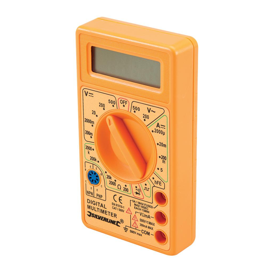
Overview

- Positive Lead
- Negative Lead
- LCD Display
- Function Selector
- 5A DC Jack
- VΩmA Jack
- COM (Common) Jack (7)
- hFE Socket
Specification
Meter category class: CAT. I, 500V
Test leads: CAT. I, 600V, 5A
Battery type: 9V 6F22 (PP3)
DC voltage: 200mV - 500V
AC voltage: 200 - 500V
DC current: 2000µA - 5A
Resistance: 200 ohm - 2000k ohm
Operating temperature: 0°C – 40°C (<75% relative humidity)
Fuses: Main circuit (F0.5A, 250V), 5A circuit (F5A, 250V)
As part of our ongoing product development, specifications of Silverline products may alter without notice
DC Voltage / Tension c.c.
Overload protection: 220V rms AC for 200mV range and 500V DC or 500V rms for all ranges
| Range | Resolution | Accuracy |
| 200mV | 100µV | ± (0.5% of reading + 3 digits) |
| 2000mV | 1mV | ± (1.0% of reading + 5 digits) |
| 20V | 10mV | |
| 200V | 100mV | |
| 500V | 1V | ± (1.2% of reading + 5 digits) |
DC Current
Overload protection: 0.5A/500V and 5A/500V fuse
| Range | Resolution | Accuracy |
| 2000µA | 1µA | ± (1.8% of reading + 2 digits) |
| 20mA | 10µA | |
| 200mA | 100µA | ± (2.0% of reading + 2 digits) |
| 5A | 10mA | ± (2.0% of reading + 10 digits) |
AC Voltage
Overload protection: 500V DC or 500V rms for all ranges
| Range | Resolution | Accuracy |
| 200V | 100mV | ± (1.2% of reading + 10 digits) |
| 500V | 1V |
Resistance
Overload protection: 15 seconds maximum 220V rms
| Range | Resolution | Accuracy |
| 200 Ω | 0.1m Ω | ± (1.0% of reading + 10 digits) |
| 2000 Ω | 1 Ω | ± (1.0% of reading + 2 digits) |
| 20K Ω | 10 Ω | |
| 200K Ω | 100 Ω | |
| 2000K Ω | 1K Ω |
Audible Continuity
Overload protection: 15 seconds maximum 220V rms
| Range | Description |
| Built-in buzzer sounds if resistance is less than 30 ± 20 Ω |
Transistor hFE test (0-1000)
| Range | Test Range | Test Current | Test Voltage |
| NPN & PNP | 0-1000 | 1b - 10µA | Vce = 3V |
| Range | Resolution | Accuracy | Overload Protection | +/- 0.5% of reading +/- 5 digits | Test Range | Test Current | Test Voltage | Built-in buzzer sounds if resistance is less than 30 ± 20 Ω | Overload protection: 0.5A/500V and 5A/500V fuse | 220V rms AC for 200mV range and 500V DC or 500V rms for all ranges |
Accuracy
Accuracy is specified for a period of one year after calibration and within temperature range 18° - 28°C with 80% max relative humidity
Assembly
- Remove the two screws from the back of the multimeter
- Take the back off and insert a 9V battery (Fig. 1)

- Connect the battery - align the battery with the connector so that the terminals on the battery and the connector snap-fit together securely
- Insert the battery into the compartment, replace the panel carefully and re-tighten the screws

Operating Notes
- If in doubt as to range required, select the highest range and then reduce it as necessary until satisfactory resolution is obtained
- If the figures '1' or '-1' are displayed, this indicates the reading is out of the set range
Voltage measurement
- Connect the red Positive Lead (1) to the VΩmA Jack (6)
- Connect the black Negative Lead (2) to the COM (Common) Jack (7)
- Rotate the Function Selector (4) to select the required voltage range in the correct DC or AC range
- Connect the test leads to the circuit being measured
- Turn on the power to the circuit being measured. The value of the voltage passing through the circuit should be displayed on the LCD Display (3), along with the polarity (if reversed only)
DC Current measurement
- For measurements up to 200mA: Connect the red Positive Lead (1) to the VΩmA Jack (6)
- For measurements above 200mA, up to max 5A: Connect the red Positive Lead (1) to the 5A Jack (5).
- Connect the black Negative Lead (2) to the COM (Common) Jack (7)
- Rotate the Function Selector (4) to select the required amperage range
- Open the circuit to be measured. Connect the test leads across the opening to create a bridge over the gap
- Switch on the power to the circuit to be measured; the value of the current passing through the circuit should be displayed on the LCD Display (3)
Resistance measurement
Note: If the resistance to be measured is part of a circuit, turn off and disconnect the power and discharge all capacitors before measurement.
- Connect the red Positive Lead (1) to the VΩmA Jack (6)
- Connect the black Negative Lead (2) to the COM (Common) Jack (7)
- Rotate the Function Selector (4) to select the required ohm range
- Connect the test leads to the circuit being measured
- The resistance value should now be displayed on the LCD Display (3)
Note: While measuring resistance about 1MΩ and above, the meter may take a few seconds to stabilise. This is normal for high resistance readings.
Diode testing
- Connect the red Positive Lead (1) to the VΩmA Jack (6)
- Connect the black Negative Lead (2) to the COM (Common) Jack (7)
- Rotate the Function Selector (4) to the setting
![]()
- Connect the red test lead to the anode of the diode to be tested and the black test lead to the cathode of the diode
- The approx. forward voltage drop of the diode should be displayed on the LCD Display (3)
Note: If the connection is reversed, only figure '1' will be displayed

Continuity testing
- Connect the red Positive Lead (1) to the VΩmA Jack (6)
- Connect the black Negative Lead (2) to the COM (Common) Jack (7)
- Rotate the Function Selector (4) to the setting
![]()
- Connect the test leads to the circuit being measured
- If continuity exists (i.e. resistance is less than approx. 50Ω), the built-in buzzer will sound

Transistor testing
- Rotate the Function Selector (4) to the 'hFE' position
- Determine whether transistor is NPN or PNP
- Locate the emitter, base and collector leads
- Insert the leads into the appropriate holes in the 'hFE' Socket (8): The left side of the socket is configured for PNP, the right side for NPN
- The approximate hFE value will be displayed on the LCD display at the testing condition of base current 10µA and Vce 3V
Test signal use
- Rotate the Function Selector (4) to the setting
![]()
- A test signal (50Hz) appears between VΩmA and COM jack, the output voltage is approx to 5V p-p with 50KΩ impedance

Storage and Maintenance

Ensure that the test leads are disconnected prior to storing or carrying out any maintenance on this tool
- Store the unit in a clean, dry environment within the temperature range -10°C to +50°C
- If the test leads are damaged in any way, replace them with new leads of the same type and specification
- When replacing internal fuses replace with exactly the same type as previously fitted (see 'Specification' and Fig. 1)
- If the unit malfunctions, have it serviced by a suitably qualified technician
- If you need to replace the battery, use method described in 'Assembly'
Contact
For technical or repair service advice, please contact the helpline on (+44) 1935 382 222.
Web: www.silverlinetools.com
UK Address: Toolstream Ltd., Boundary Way, Lufton Trading Estate, Yeovil, Somerset, BA22 8HZ, United Kingdom EU Address: Toolstream B.V., Holtum-Noordweg 11, Unit 4, 6121 RE Born, The Netherlands
Troubleshooting
| Problem | Possible cause | Solution |
Lowest digit of value is unstable | — | Normal operation for some measuring |
Display value erratic | Intermittent connection in one of the test leads | Replace test leads ensuring they are the correct specification |
| Battery low | Replace battery |
Multimeter Safety

The following are important safety points to avoid electric shock, personal injury and electrocution.

When using the probes, keep fingers behind the finger guards.
When an input terminal is connected to a dangerous live voltage, this voltage can occur at other terminals on the meter.
Some functionality of this tool is only suitable for those skilled in electrical work. If in doubt about your capabilities, do not use this tool.
- Do not use the meter if it is damaged. Inspect the case. Pay particular attention to the insulation surrounding the connectors
- Do not use the meter if it operates abnormally. It may give a false safe measurement. If in doubt, have the meter serviced
- Inspect the test leads and probes for damaged insulation or exposed metal. Check the test leads regularly for continuity to prevent dangerous false readings. Replace damaged test leads before using the meter
- Do not operate the meter around explosive gas, vapour or dust
- Do not use in wet or damp conditions and ensure the meter and test leads are completely dry before use. If using outside with open electrical connections, ensure they are protected from rain
- Do not apply more than the rated voltage, as marked on the meter, between terminals or between any terminal and earth ground
- Do not exceed the rated voltage and current indicated on the test leads
- Use caution when working with voltages above 30V ac rms, 42V peak, or 60V dc. Such voltages pose a shock hazard
- Connect the common test lead before you connect the live test lead. When you disconnect test leads, disconnect the live test lead first
- Do not operate the meter with the battery cover or portions of the case removed or loosened
- Do not touch any exposed conductor directly with hands or skin
- Do not use the supplied test leads with other equipment. This could damage the test leads or the other equipment and could create a safety hazard
- Do not change settings or make adjustments to the meter close to live cables or exposed conductors. Change settings and make adjustments in a safe area
- Do not ground yourself when taking electrical measurements. Ensure you are isolated by wearing rubber shoes with no part of your body resting against an earthed surface, for example pipes, fixtures etc.
Documents / Resources
References
Download manual
Here you can download full pdf version of manual, it may contain additional safety instructions, warranty information, FCC rules, etc.
Download Silverline 589681 - Digital Multimeter AC & DC Manual
Advertisement


Need help?
Do you have a question about the 589681 and is the answer not in the manual?
Questions and answers