Advertisement
Quick Links
Thank you for choosing this product.
This product is guaranteed to be free of defects in materials and workmanship for a period
of 3 years from the purchase date.
Users Manual
If you experience a problem, return the product direct to us, with the original receipt at :
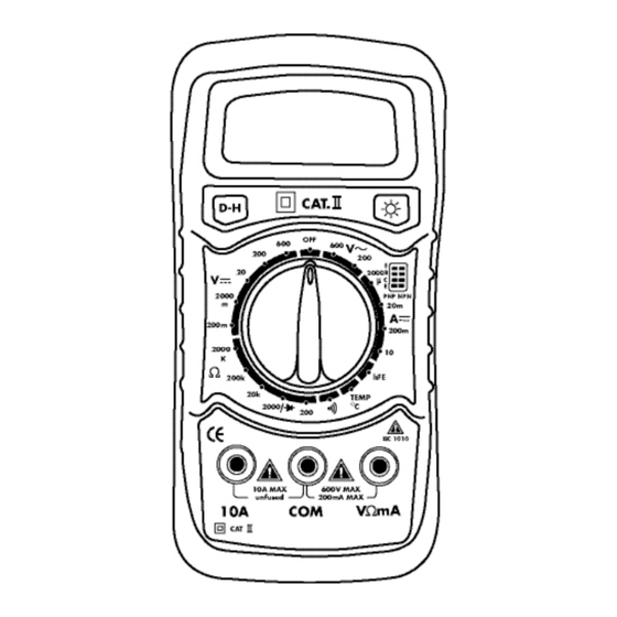
Expert Digital Multimeter
Silverline Tools Limited
Product Code 513121
PO Box 2988
© May 2006
Yeovil
BA21 1WU
We do not refund carriage. This guarantee is for Great Britain only and does not affect your
statutory rights. As you would expect fair wear and tear are not covered.
Advertisement

Subscribe to Our Youtube Channel
Related Manuals for Silverline 513121


Summary of Contents for Silverline 513121
- Page 1 3 years from the purchase date. Users Manual If you experience a problem, return the product direct to us, with the original receipt at : Expert Digital Multimeter Silverline Tools Limited Product Code 513121 PO Box 2988 © May 2006 Yeovil BA21 1WU We do not refund carriage.
-
Page 2: Digital Multimeter
SAFETy INSTRUCTIONS SPECIFICATIONS Transistor hFE Test range situation and the higher range has to be selected. It is important to read and understand your instruction manual. • Max voltage between input terminal and earth ground: CAT • " " means you can't input voltage higher than 600V, it's Learn the tools application, as well as it's limitations and the III 600V. Range Test Range Test Current/Voltage possible to show higher voltage, but it may destroy the inner potential hazards associated with this tool. • Over-range indication: display "1" for the significant digit. circuit or pose a shock hazard. NPN & PNP 0-1000 Ib=10uA/Vce=3V • Automatic display if negative polarity "_". • Always exercise caution when working with electric, if in any ADDITIONAL SAFETy INFORMATION FOR MULTIMETER • Low battery indication: ' ' displayed. doubt seek advice from a qualified electrician. • The meter is designed according to IEC-1010 with an • Max LCD display: 1999 (3 ) digits). - Page 3 • Connect the red lead to the anode and the black lead to the cathode of the diode under testing. Note: • The meter will show approximate forward voltage drop of the diode. • If the lead connections is reversed, only '1' will be displayed. Continuity Testing • Connect the black test lead to COM jack and the red to VΩmA jack. • Set the rotary switch at the range position. • Connect test leads across two points of the circuit under testing. • If continuity exists (i.e. resistance less than about 50Ω), the built-in buzzer will sound. Note: If the input is an open circuit, the figure '1' will be displayed. Measuring Capacitor • Connect the black test lead to Cx-jack and the red to Cx+ jack. • Set the rotary switch at the desired 20uF/200nF range position. • Before inserting capacitor under measurement into capacitance testing socket be sure that the capacitor has been discharged fully. Measuring Battery • Load resistance 1.5v range: 36Ω 9V range: 360Ω 12V range: 450Ω...
Need help?
Do you have a question about the 513121 and is the answer not in the manual?
Questions and answers