StetSom STX2448 - DIGITAL AUDIO PROCESSOR Manual
- User manual (46 pages) ,
- User manual (19 pages) ,
- User manual (79 pages)
Advertisement
- 1 Introduction
- 2 Features
- 3 Before installing
- 4 Processor presentation
- 5 Installation and Power Supply
- 6 Use of 12V Power Supply
- 7 Controls and indicators
- 8 Settings and Features Map
- 9 MAIN MENU: AUDIO
- 10 MAIN MENU: SAVE / LOAD
- 11 MAIN MENU: COPY CHANNEL
- 12 MAIN MENU: SECURITY
- 13 MAIN MENU: TOOLS
- 14 MAIN MENU: SCREENSAVER
- 15 MAIN MENU: LANGUAGE
- 16 MAIN MENU: SEQUENCER
- 17 Technical Specifications
- 18 Documents / Resources
Introduction
This product has been carefully developed by a team that is passionate in audio and technology, aiming to provide you an experience of excellency and quality. Explore all the audio adjustment and equalization features so that you can fully enjoy your music with high sound fidelity
Features
The processor has 2 input channels (A and B) and 4 independent output channels (1, 2, 3, and 4), as follows:
| INPUTS | MAIN IN: RCA Connection (A and B) |
| HIGH-IN: WIRE Connection (A and B) | |
| OUTPUTS | OUT 1: RCA (L + R) |
| OUT 2: RCA (L + R) | |
| OUT 3: RCA (L + R) | |
| OUT 4: RCA (L + R) |
INPUT CONNECTIONS
 HIGH CONNECTION (WIRE)
Common in vehicle original radios and players.

RCA CONNECTION (LINE) Common in market radios and sound equipment.
The digital processing capabilities allow precise audio adjustments through various functions and features integrated into the processor:
- DSP FLOAT MODE, provides different flows and features;
- INPUT GAIN
- INPUT GRAPHIC EQUALIZER;
- SUBHARMONIC bass;
- OUTPUT MODE, allows flexibility of features for each output;
- UTPUT PARAMETRIC EQUALIZERS;
- ROUTING between inputs and outputs;
- HIGH-PRECISION CROSSOVER (with Butterworth, Linkwitz-Riley, and Bessel filters);
- HIGH-PRECISION DELAY;
- PHASE INVERSION;
- RMS and PEAK LIMITER com ajuste de Threshold, Attack, Hold e Release;
- GENERAL VOLUME, GAIN and MUTE for each output;
- AUTOMATIC SAVE and LOAD to save and load audio parameters;
- SECURITY PASSWORD to lock parameter modifications;
- FREQUENCY and SWEEP GENERATOR;
- INTEGRATED SEQUENCER for remote activation with configurable time.
Before installing
Carefully read the manual before using the product.
- All product connections must be made with it turnedOFF.
- It is mandatory to install a fuse between the product and the battery for protection in case of overload. The fuse should be compatible with the product's power consumption and installed as close as possible to the battery.
- Use the recommended gauges in this manual to prevent cable overheating and achieve optimal performance.
- Keep the cables as short as possible to enhance sound fidelity and prevent potential power loss.
- Distribute the installation cables as far away as possible from the vehicle's original wiring, as it may cause interference and noise in your audio system.
- Install it in a stable, well-ventilated, and dry location.
- The installation should be done by a qualified professional.
If you have any questions, inquire with the store where the installation was performed or contact our Customer Service: 018 2104 9412.
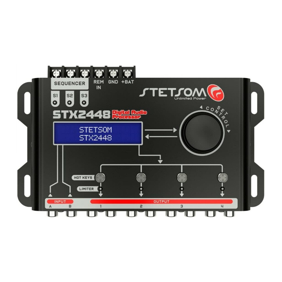
Processor presentation


- INPUT: The processor has two types of input connections: RCA and HIGH (Wire Input). Both share the same input channels (A and B), use them according to your needs.
Using RCA and HIGH INPUT connections simultaneously may generate unwanted noises or audio issues. - OUTPUT: It has 4 independent RCA outputs (L+R) for connecting amplifiers and other devices. These outputs are processed with the audio parameter changes made by the user.
- INPUT LEVEL: Allows adjustment of the input audio signal levels. This control has two LEDs (channels A and B) indicating when the input signal is saturated (CLIP). The signal adjustment operates simultaneously on the MAIN (RCA) and HIGH (Wire) inputs.


- DISPLAY LCD: Allows visualization and interaction with the processor's system.
- SEQUENCER: These connections enable the activation of various products in a sequenced manner with configurable timing. Make the connection using a cable of at least AWG 18.

Installation and Power Supply

- REMOTE CONTROL CONNECTION (REM): Responsible for triggering the processor when this connection is powered. Connect it to the remote output of the radio/ player using a cable with a gauge of 13 AWG or use an on/off switch connected to a 12V voltage for manual activation.
- POSITIVE CONNECTOR
![]() : Connect it to the positive pole of the battery or a 12V power source using a cable with a minimum gauge of AWG 13. For vehicle battery usage, use a 1A fuse to protect the electrical system, installing it at a maximum of 12" from the battery.
: Connect it to the positive pole of the battery or a 12V power source using a cable with a minimum gauge of AWG 13. For vehicle battery usage, use a 1A fuse to protect the electrical system, installing it at a maximum of 12" from the battery. - NEGATIVE/GROUND CONNECTOR : Connect to the negative pole of the battery or power source using a cable with a gauge of 13 AWG.

Use of 12V Power Supply

Controls and indicators

- ENCODER CONTROL: Navigation and interaction control for the processor's system functions and features.
ENCODER ROTATION
Navigation function through system features and parameter adjustment.
![]()
ENCODER TOUCH
Tap and release: Functions include entering, selecting, and skipping parameters.
Tap and hold: Function to return to the previous screen or main menu.
![]()
- HOTKEYS BUTTONS: Dedicated buttons for selecting the channel to apply parameters or for the MUTE function.
TAP AND RELEASE
Tap for quick selection of the channel where audio parameters will be applied.
TOUCH AND HOLD
Hold to ENABLE or DISABLE the MUTE mode for the channel.

- LIMITER INDICATOR LEDs:
These LEDs indicate when the LIMITER feature is active on the indicated channel. They are also used as saturation indicators for the signal in the output channel.


Settings and Features Map
Find the desired function using the illustration below with all the tabs for the processor settings and features:
THE FEATURES WILL BE AVAILABLE ACCORDING TO THE OPERATING FLOATING DSP MODE (STD OR PRO).

MAIN MENU: AUDIO
> DSP FLOAT MODE
The DSP Floating feature allows the processor to be loaded with different audio streams and resources, expanding the range of possibilities for configuring various systems. The available modes are:
STD: Input Gain, Graphic EQ 15-Band, Graphic EQ Presets, Output Parametric Equalizers, Routing, Crossover, Delay/Alignment, Phase Inversion, RMS Limiter, Output Gain, and Mute.
PRO: Input Gain, Sub Harmonic Bass, Output Parametric Equalizers, Routing, Crossover, Delay/Alignment, Phase Inversion, Peak Limiter, RMS Limiter, Output Gain, and Mute.
The processor comes factory-set with the DSP FLOAT mode: PRO.


> OUTPUT MODE
This feature allows for flexible distribution of processing resources according to the specific requirements for each audio output. It enables the selection of the operating mode for each output, varying the number of parametric equalizers and the maximum attenuation of the crossover filters.

In the example, Output 1 has been configured with 3 parametric equalizers, a high-pass filter of up to 36dB/8th, and a low-pass filter of up to 24dB/8th.


> INPUT GAIN
Adjust individual input gains within the range of ±12dB with a 0.1dB.

> INPUT GRAPHIC EQUALIZER (STD)
This function is available when the DSP FLOAT mode is set to 'std."
The input graphic equalizer features 15 bands with frequencies equally spaced in 2/3 of an octave, ranging from 25Hz to 16kHz. It allows gain adjustment of ±12dB with a 0.1dB.

The graphic equalizer operates on both inputs simultaneously.
> PRESET GRAPHIC EQ (STD)
This function is available when the DSP FLOAT mode is set to 'std."
The processor provides 12 preset graphic equalization settings that can be selected from the "PREDEF GEQ IN" menu in the audio settings:
")
- FLAT
- LOUDNESS
- BASSBOOST
- MID BASS
- TREBLE BOOST
- POWERFUL
- ELECTRONIC
- ROCK
- HIP HOP
- POP
- VOCAL
- PANCADAO
> SUBHARMONIC BASS (PRO)
Function available when the DSP FLOAT mode is set to "PRO."
This function is capable of generating sub-harmonic frequencies for the A+B signal (available as a routing option). It enhances and extends the low frequencies (bass), making them more pronounced. It is possible to define the maximum sub-harmonic frequency that can be generated, as well as its intensity.
")
 The SUBHARMONIC BASS produces low frequencies that some speakers may not be designed to reproduce. Pay attention to the speaker's lowest frequency response and correctly configure the high-pass filter (H.P.F).
> OUTPUT PARAMETRIC EQUALIZER
Choose gain/attenuation at a specific frequency, as well as the bandwidth of this equalizer through the "Q" factor. The lower the "Q," the wider the bandwidth of this equalization band, affecting neighboring frequencies to a greater extent.
The number of parametric equalizers available in each output depends on the configured DSP FLOAT MODE and OUTPUT MODE.


> AUDIO INPUT/OUTPUT (ROUTING)
Select the audio source for each output:
A, B, or A+B (SUM) FOR EACH OUTPUT.
Use the "ENCODER" to change the audio source for the selected channel. To choose another channel, give a single tap on the corresponding "HOTKEY" shortcut key.

> CROSSOVER
In the crossover menu, each single tap on the "ENCODER" changes the parameter in editing, including output, filter type, frequency, and attenuation/topology. To select another output channel for editing, give a single tap on the corresponding "HOTKEY" shortcut key.
The maximum attenuation available for each filter on each output depends on the configured DSP FLOAT MODE and OUTPUT MODE.
Precisely define the cutoff frequencies of the low-pass filters (L.P.F.), high-pass filters (H.P.F.), attenuations, and filter topology individually for each output.

AVAILABLE FILTERS AND ATTENUATIONS ARE:
Butterworth: 12/18/24/30/36/42/48 dB/8ª
Linkwitz-Riley: 12/18/24/30/36/42/48 dB/8ª
Bessel: 12/18/24/30/36/42/48 dB/8ª
> ALIGNMENT (DELAY)
Digitally align the transducers (speakers) by correcting time in the DSP. This ensures that the sounds from all speakers reach the listener simultaneously, preventing frequency cancellations and improving sound fidelity. The adjustment can be done as follows:
- Identify the coil farthest from the listener or the front panel of the box, and use this coil as a reference;
![]()
- Measure the distance from the other coils to the reference coil. These distances will be used in configuring the delay for each output channel.

Example measurements:

> PHASE
This function is designed to address frequency cancellation issues. On this screen, you can independently invert the phase of all outputs.
By turning the "ENCODER," you can change the phase (0º or 180º) of the corresponding output. To select another channel, give a simple tap on the corresponding "HOTKEY" shortcut key.

> LIMITER PEAK (PRO) e RMS
The Limiter Peak function will be disponible when the DPS FLOAT mode is active in "Pro" mode. The function Limiter RMS will be disponible in both modes (Stand and Pro).
LIMITER PEAK: The peak limiter function is a type of compression that reduces the highest peaks levels in your signal, preventing them from exceeding the maximum level supported by your system. This peak limitation is useful to ensure that signals do not exceed the absolute maximum specifications of amplifiers and speakers. However, peak limitation does not affect the overall level or average intensity of the sound. For this reason, RMS limiting becomes necessary.
LIMITER RMS: The RMS limiter function is a type of compression that reduces the level of your signal based on the average or RMS value. The limiter RMS is useful for limiting the overall level or overage of the sound, as well as ensuring that signals do not exceed the continuous operating levels of amplifiers and speakers.
The parameters found in the limiters are:
THRESHOLD: Sets a threshold for the Limiter's action: when this threshold is exceeded, the Limiter is triggered.
ATTACK (Available only in the RMS Limiter): Sets how quickly the Limiter responds/acts when the signal exceeds the Threshold.
HOLD: Sets the time that the Limiter will maintain attenuation before the gain begins to return to the normal level.
RELEASE: Sets the time for recovery and return of gain to the normal level.
Besides the manual adjustments of the Attack, Hold and Release, it is possible to allow the "AUTO" mode, where these parameters are controlled dynamically in real time by the system "Automatic Dynamic Limiter", providing ideal conditions for sound fidelity
 e RMS")
> OUTPUT GAIN
Adjust individual gains on the outputs in the range of -45dB to ±15dB, with a step of 0.1dB, and overall volume from 0 to 100%.

> MUTE
The outputs can be quickly turned on or off individually by holding down the "HOTKEY" shortcut key for the corresponding output.
 | BLUE LED Output channel ON. |  | RED LED Output channel OFF (MUTE). |
In MUTE screen, it is possible to turn on/ off all channels individually or all outputs simultaneously using the option "MUTE ALL (ENTER)" or "ON ALL (ENTER)", by confirming it with a simple tap on "ENCODER".

MAIN MENU: SAVE / LOAD
It is possible to save up to 3 profiles in memory to be loaded whenever desired, containing all the parameters adjusted in that profile with a customized name of up to 15 characters.

In addition to these profiles, the processor has an automatic saving feature where all changed parameters and configurations are saved automatically. If the product is turned off during adjustments, these settings will not be lost.
To load previously saved parameters, use the "LOAD" menu. It is also possible to load factory parameters through the "PADRAO" (DEFAULT) memory

If you want to restore all the factory parameters of the processor, keep pressed simultaneously the shortcut keys "HOTKEYS" of the outputs (1, 2 and 3) and turn on the processor.

MAIN MENU: COPY CHANNEL
Allows copying all the audio settings from one output channel to another.
The copied parameters are: PARAMETRIC OUTPUT EQUALIZER, ROUTING, CROSSOVER, ALIGNMENT, PHASE INVERTION, LIMITER, GAIN and MUTE

MAIN MENU: SECURITY
Lock the processor parameters, including the save and load configuration functions. The processor lock/unlock is configured through the"Bloq./Desbloq.". The function for turning on/off the channels are not affected.
DEFAULT PASSWORD
(Uppercase Letters): STET

To change the processor's password, use the option "Change Password". The password must contain 4 digits and can contain letters and numbers.

MAIN MENU: TOOLS
The processor has two tools to assist you in adjusting your sound system: "TONE GENERATOR" and "FREQUENCY SWEEP". These tools serve as signal sources for all outputs. During their use, inputs A and B receive the internal signals from these tools. This way, the signals will undergo the treatments and configurations of each output.
> TONE GENERATOR
Permit generating a specific frequency with gain control. Each press on "ENCODER" changes the parameter of editing between frequencies, gain and ON/OFF. With the generator turned on it is still possible to change the frequency in real time, including modify other audio parameters of the processor.

> SWEEP
Allows performing a frequency sweep with the option to select the initial and final frequency, gain, sweep speed, and ON/OFF. When activating the sweep, it enters a continuous cycle; to end it, simply press one of the "HOTKEYS" or move the "ENCODER".

MAIN MENU: SCREENSAVER
The processor has a screen protection function that is displayed when turning on the product or returning from the main menu. It is possible to set a scrolling text of up to 15 characters.

MAIN MENU: LANGUAGE
Change the language of the system between English, Spanish, and Portuguese

MAIN MENU: SEQUENCER
Enables remote activation of various products sequentially.
The processor has three outputs (S1, S2, and S3) that are turned on or off sequentially as soon as the processor receives a signal at the remote input (REM IN).
The activation and deactivation times can be configured separately, allowing different activation and deactivation times (configurable values from 0 to 4 seconds).

If the preset time is 0 seconds, all outputs will be activated/ deactivated simultaneously
It is possible to turn on/off independently the output of the sequencer. When the output is configured as TURNED OFF, the same will not activate when the processor turns on again, until this configuration changes.

Example of the feature installation:
For connections to the remote output, use cables of at least 18 AWG

Technical Specifications
| Number of input channels: | 2 |
| Number of output channels: | 4 |
| Input gain: | IN A: ±12 dB / IN B: ±12 dB |
| Graphical equalizer¹: | 15 Bands: Gain ±12dB, customized e 12 presets |
| Subharmonic BASS²: | Frequency: 40Hz ~ 120Hz and adjustable again |
| Output parametric equalizer³: | Frequency: 10Hz ~ 22KHz Gain ±12dB and Q Factor = 0,4 ~ 10,0 |
| Routing of inputs to outputs: | A, B or A+B |
| Crossover³: | HPF & LPF Butterworth: 12/18/24/30/36/42/48 dB/8ª Linkwitz-Riley: 12/18/24/30/36/42/48 dB/8ª Bessel: 12/18/24/30/36/42/48 dB/8ª |
| Alignment/Delay: | 0ms ~ 8ms (275cm) |
| Phase inversion: | 0º ~ 180º |
| Limiter Peak²: | Threshold, Hold e Release |
| Limiter RMS: | Threshold, Attack, Hold e Release |
| Output gain: | Master level: 0% a 100% and gain: -45dB a +15dB |
| Memory: | Auto-Save + 3 Memory Positions |
| Safety: | Security password of 4-digits |
| Generator/Frequency Sweep: | 10Hz ~ 22KHz and adjustable again |
| Screen Protector: | Editable Text (up to 15 characters) |
| Languages: | Portuguese, English and Spanish |
| Latency: | 1,08ms |
| Input impedance: | RCA IN: 55K Ohms / HIGH IN: 1K Ohms |
| Output impedance: | 47 Ohms |
| Maximum input voltage: | RCA IN: 5V RMS / 14,1 Vpp / +16,2 dBu HIGH IN: 20V RMS / 56,5 Vpp / +28,2 dBu |
| Maximum output voltage: | 2V RMS / 5,6 Vpp / +8,2 dBu |
| Max. Output current: | 180 mA (per output) |
| Output saturation indicator: | 1 per output (linked to the limiter) |
| Signal to noise ratio: | >90dB |
| Total harmonic distortion: | <0,01% |
| Channels separation: | >80dB |
| Frequency response: | 10Hz ~ 22,5KHz @ -1dB |
| Power supply: | 9V ~ 16V DC |
| Maximum current consumption: | 350mA @ 12,6V DC |
| Dimension (H x W x L): | 1.44" x 9.02" x 4.47" |
| Weight: | 1.10 lb |
 Any updates made to this manual will be available for consumer reference free of charge on the brand's website. It is recommended to consult the updated manual whenever necessary
¹ Disponible only in the DSP Float BASIC mode.
² Disponible only in the DSP Float PRO mode.
³ Quantity of parametric equalizers and the maximum attenuation of crossovers depends on the configured OUTPUT MODE for each output.
Phone: BR +55 18 2104-9412
E-mail: suporte@stetsom.com.br
Site: www.stetsom.com
Documents / Resources
References
Download manual
Here you can download full pdf version of manual, it may contain additional safety instructions, warranty information, FCC rules, etc.
Advertisement


Need help?
Do you have a question about the STX2448 and is the answer not in the manual?
Questions and answers