Arduino Nano 33 IoT (ABX00027) - Controller Manual
- Product reference manual (18 pages) ,
- Product reference manual (17 pages) ,
- Product reference manual (16 pages)
Advertisement
Description
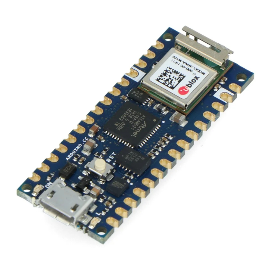
The Arduino® Nano 33 IoT and Arduino Nano 33 IoT with headers are a miniature sized module containing a Cortex M0+ SAMD21 processor, a Wi-Fi® + Bluetooth® module based on ESP32, a crypto chip which can securely store certificates and pre-shared keys and a 6 axis IMU. The module can either be mounted as a DIP component (when mounting pin headers), or as a SMT component, directly soldering it via the castellated pads.
Target areas:
Maker, enhancements, basic IoT application scenarios
Features
- SAMD21G18A
- Processor
- 256 kB Flash
- 32 kB Flash
- Power On Reset (POR) and Brown Out Detection (BOD)
- Peripherals
- 12 channel DMA
- 12 channel event system
- 5x 16 bit Timer/Counter
- 3x 24 bit timer/counter with extended functions
- 32 bit RTC
- Watchdog Time
- CRC-32 generator
- Full speed Host/Device USB with 8 end points
- 6x SERCOM (USART, I2C, SPI, LIN)
- Two channel I2S
- 12 bit 350ksps ADC (up to 16 bit with oversampling)
- 10 bit 350ksps DAC
- External Interrupt Controller (up to 16 lines)
- Processor
- Nina W102
- Module
- Dual Core Tensilica LX6 CPU at up to 240MHz
- 448 kB ROM, 520 kB SRAM, 2MB Flash
- Wi-Fi®
- IEEE 802.11b up to 11Mbit IEEE 802.11g up to 54MBit
- IEEE 802.11n up to 72MBit
- 2.4 GHz, 13 channels
- 96 dBm sensitivity
- Bluetooth® BR/EDR
- Max 7 peripherals
- 2.4 GHz, 79 channels
- Up to 3 Mbit/s
- 8 dBm output power at 2/3 Mbit/s
- 11 dBm EIRP at 2/3 Mbit/s
- 88 dBm sensitivity
- Bluetooth® Low Energy
- Bluetooth® 4.2 dual mode
- 2.4GHz 40 channels
- 6 dBm output power
- 9 dBm EIRP
- 88 dBm sensitivity Up to 1 Mbit/
- MPM3610 (DC-DC)
- Regulates input voltage from up to 21V with a minimum of 65% efficiency @minimum load More than 85% efficiency @12V
- ATECC608A (Crypto Chip)
- Cryptographic co-processor with secure hardware based key storage
- Protected storage for up to 16 keys, certificates or data
- ECDH: FIPS SP800-56A Elliptic Curve Diffie-Hellman
- NIST standard P256 elliptic curve support
- SHA-256 & HMAC hash including off-chip context save/restore AES-128 encrypt/decrypt, galois field multiply for GCM
- LSM6DSL (6 axis IMU)
- Always-on 3D accelerometer and 3D gyroscope
- Smart FIFO up to 4 KByte based
- ±2/±4/±8/±16 g full scale
- ±125/±250/±500/±1000/±2000 dps full scale
- Module
The Board
As all Nano form factor boards, Nano 33 IoT and Nano 33 IoT with headers does not have a battery charger but can be powered through USB or headers.
NOTE: Nano 33 IoT and Nano 33 IoT with headers only supports 3.3V I/Os and is NOT 5V tolerant so please make sure you are not directly connecting 5V signals to this board or it will be damaged. Also, as opposed to Arduino Nano boards that support 5V operation, the 5V pin does NOT supply voltage but is rather connected, through a jumper, to the USB power input.
Application Examples
Weather station: Using the Nano 33 IoT or Nano 33 IoT with headers together with a sensor and a OLED display, we can create a small weather station communicating temperature, humidity etc. directly to your phone.
Air quality monitor: Bad air quality may have serious effects on your health. By assembling the board, with a sensor and monitor you can make sure that the air quality is kept in indoor-environments. By connecting the hardware assembly to an IoT application/API, you will receive real time values.
Air drum: A quick and fun project is to create a small air drum. Connect your board and upload your sketch from the Arduino Cloud Editor and start creating beats with your audio workstation of your choice.
Ratings
Recommended Operating Conditions
| Symbol | Description | Min | Max |
| Conservative thermal limits for the whole board: | -40°C ( 40°F) | 85°C ( 185°F) |
Power Consumption
| Symbol | Description | Min | Typ | Max | Unit |
| VINMax | Maximum input voltage from VIN pad | -0.3 | - | 21 | V |
| VUSBMax | Maximum input voltage from USB connector | -0.3 | - | 21 | V |
| PMax | Maximum Power Consumption | - | - | TBC | mW |
Functional Overview
Board Topology
Board topology top

| Ref. | Description | Ref. | Description |
| U1 | ATSAMD21G18A Controller | U3 | LSM6DSOXTR IMU Sensor |
| U2 | NINA-W102-00B Wi-Fi®/Bluetooth® LE Module | U4 | ATECC608A-MAHDA-T Crypto Chip |
| J1 | Micro USB Connector | PB1 | IT-1185-160G-GTR Push button |
Board topology bottom

| Ref. | Description | Ref. | Description |
| SJ1 | Open solder bridge (VUSB) | SJ4 | Closed solder bridge (+3V3) |
| TP | Test points | xx | Lorem Ipsum |
Processor
The Main Processor is a Arm® Cortex®-M0+ running at up to 48 MHz. Most of its pins are connected to the external headers, however some are reserved for internal communication with the wireless module and the on-board internal I2C peripherals (IMU and Crypto).
NOTE: As opposed to other Arduino Nano boards, pins A4 and A5 have an internal pull up and default to be used as an I2C Bus so usage as analog inputs is not recommended.
Communication with NINA W102 happens through a serial port and a SPI bus through the following pins.
| SAMD21 Pin | SAMD21 Acronym | NINA Pin | NINA Acronym | Description |
| 13 | PA08 | 19 | RESET_N | Reset |
| 39 | PA27 | 27 | GPIO0 | Attention Request |
| 41 | PA28 | 7 | GPIO33 | Acknowledge |
| 23 | PA14 | 28 | GPIO5 | SPI CS |
| 21 | GPIO19 | UART RTS | ||
| 24 | PA15 | 29 | GPIO18 | SPI CLK |
| 20 | GPIO22 | UART CTS | ||
| 22 | PA13 | 1 | GPIO23 | SPI MISO |
| 21 | PA12 | 36 | GPIO12 | SPI MOSI |
| 31 | PA22 | 23 | GPIO3 | Processor TX Nina RX |
| 32 | PA23 | 22 | GPIO1 | Processor RX Nina TX |
Wi-Fi®/Bluetooth® Communication Module
Nina W102 is based on ESP32 and is delivered with a pre-certified software stack from Arduino. Source code for the firmware is available [13].
NOTE: Reprogramming the wireless module's firmware with a custom one will invalidate compliance with radio standards as certified by Arduino, hence this is not recommended unless the application is used in private laboratories far from other electronic equipment and people. Usage of custom firmware on radio modules is the sole responsibility of the user.
Some of the module's pins are connected to the external headers and can be directly driven by ESP32 provided SAMD21's corresponding pins are aptly tri-stated. Below is a list of such signals:
| SAMD21 Pin | SAMD21 Acronym | NINA Pin | NINA Acronym | Description |
| 48 | PB03 | 8 | GPIO21 | A7 |
| 14 | PA09 | 5 | GPIO32 | A6 |
| 8 | PB09 | 31 | GPIO14 | A5/SCL |
| 7 | PB08 | 35 | GPIO13 | A4/SDA |
Crypto
The crypto chip in Arduino IoT boards is what makes the difference with other less secure boards as it provides a secure way to store secrets (such as certificates) and accelerates secure protocols while never exposing secrets in plain text.
Source code for the Arduino Library that supports the Crypto is available [14]
IMU
The board has an embedded 6-axis IMU which can be used to measure board orientation (by checking the gravity acceleration vector orientation) or to measure shocks, vibration, acceleration and rotation speed.
Source code for the Arduino Library that supports the IMU is available [15]
Power Tree

Board Operation
Getting Started - IDE
If you want to program your board while offline you need to install the Arduino Desktop IDE [1] To connect the Nano 33 IoT to your computer, you'll need a Micro-B USB cable. This also provides power to the board, as indicated by the LED.
Getting Started - Arduino Cloud Editor
All Arduino boards, including this one, work out-of-the-box on the Arduino Cloud Editor [2], by just installing a simple plugin.
The Arduino Cloud Editor is hosted online, therefore it will always be up-to-date with the latest features and support for all boards. Follow [3] to start coding on the browser and upload your sketches onto your board.
Getting Started - Arduino Cloud
All Arduino IoT enabled products are supported on Arduino Cloud which allows you to Log, graph and analyze sensor data, trigger events, and automate your home or business.
Sample Sketches
Sample sketches for the Nano 33 IoT can be found either in the "Examples" menu in the Arduino IDE or in the "Documentation" section of the Arduino Docs website [4].
Online Resources
Now that you have gone through the basics of what you can do with the board you can explore the endless possibilities it provides by checking exciting projects on Arduino Project Hub [5], the Arduino Library Reference [6] and the online store [7] where you will be able to complement your board with sensors, actuators and more
Board Recovery
All Arduino boards have a built-in bootloader which allows flashing the board via USB. In case a sketch locks up the processor and the board is not reachable anymore via USB it is possible to enter bootloader mode by double-tapping the reset button right after power up.
Connector Pinouts
Pinout

USB
| Pin | Function | Type | Description |
| 1 | VUSB | Power | Power Supply Input. If board is powered via VUSB from header this is an Output (1) |
| 2 | D- | Differential | USB differential data - |
| 3 | D+ | Differential | USB differential data + |
| 4 | ID | Analog | Selects Host/Device functionality |
| 5 | GND | Power | Power Ground |
- The board can support USB host mode only if powered via the VUSB pin and if the jumper close to the VUSB pin is shorted.
Headers
The board exposes two 15 pin connectors which can either be assembled with pin headers or soldered through castellated vias.

Debug
On the bottom side of the board, under the communication module, debug signals are arranged as 3x2 test pads with 100 mil pitch. Pin 1 is depicted in Figure 3 – Connector Positions
| Pin | Function | Type | Description |
| 1 | +3V3 | Power Out | Internally generated power output to be used as voltage reference |
| 2 | SWD | Digital | SAMD11 Single Wire Debug Data |
| 3 | SWCLK | Digital In | SAMD11 Single Wire Debug Clock |
| 4 | UPDI | Digital | ATMega4809 update interface |
| 5 | GND | Power | Power Ground |
| 6 | RST | Digital In | Active low reset input |
Mechanical Information
Board Outline and Mounting Holes
The board measures are mixed between metric and imperial. Imperial measures are used to maintain a 100 mil pitch grid between pin rows to allow them to fit a breadboard whereas board length is Metric.
Layout

Connector Positions
The view below is from top however it shows Debug connector pads which are on the bottom side. Highlighted pins are pin 1 for each connector' Top view:
Top side connectors

Bottom view:
Bottom side connectors

Company Information
| Company name | Arduino S.r.l |
| Company Address | Via Andrea Appiani, 2520900 MONZA |
Reference Documentation
Documents / Resources
References
![www.arduino.cc]() https://www.arduino.cc/en/software
https://www.arduino.cc/en/softwarehttps://docs.arduino.cc/arduino-cloud/guides/editor/
https://docs.arduino.cc
Arduino Project Hub
![www.arduino.cc]() Arduino Reference - Arduino Reference
Arduino Reference - Arduino Reference![store.arduino.cc]() Arduino Official Store | Boards Shields Kits Accessories
Arduino Official Store | Boards Shields Kits Accessories![forum.arduino.cc]() Arduino Forum
Arduino Forumhttps://ww1.microchip.com/downloads/aemDocuments/documents/MCU32/ProductDocuments/DataSheets/SAM-D21DA1-Family-Data-Sheet-DS40001882G.pdf
![content.u-blox.com]() https://content.u-blox.com/sites/default/files/NINA-W10_DataSheet_UBX-17065507.pdf
https://content.u-blox.com/sites/default/files/NINA-W10_DataSheet_UBX-17065507.pdfhttps://ww1.microchip.com/downloads/aemDocuments/documents/SCBU/ProductDocuments/DataSheets/ATECC608A-CryptoAuthentication-Device-Summary-Data-Sheet-DS40001977B.pdf
![www.monolithicpower.com]() https://www.monolithicpower.com/pub/media/document/MPM3610_r1.01.pdf
https://www.monolithicpower.com/pub/media/document/MPM3610_r1.01.pdf![github.com]() GitHub - arduino/nina-fw: Firmware for u-blox NINA W102 WiFi/BT module
GitHub - arduino/nina-fw: Firmware for u-blox NINA W102 WiFi/BT module![github.com]() GitHub - arduino-libraries/ArduinoECCX08
GitHub - arduino-libraries/ArduinoECCX08![github.com]() GitHub - stm32duino/LSM6DSL: Arduino library to support the LSM6DSL 3D accelerometer and 3D gyroscope
GitHub - stm32duino/LSM6DSL: Arduino library to support the LSM6DSL 3D accelerometer and 3D gyroscope
Download manual
Here you can download full pdf version of manual, it may contain additional safety instructions, warranty information, FCC rules, etc.
Advertisement


Need help?
Do you have a question about the Nano 33 IoT and is the answer not in the manual?
Questions and answers