Table of Contents
Advertisement
Quick Links
Advertisement
Table of Contents

Subscribe to Our Youtube Channel
Related Manuals for Luthor TLM-808


Summary of Contents for Luthor TLM-808
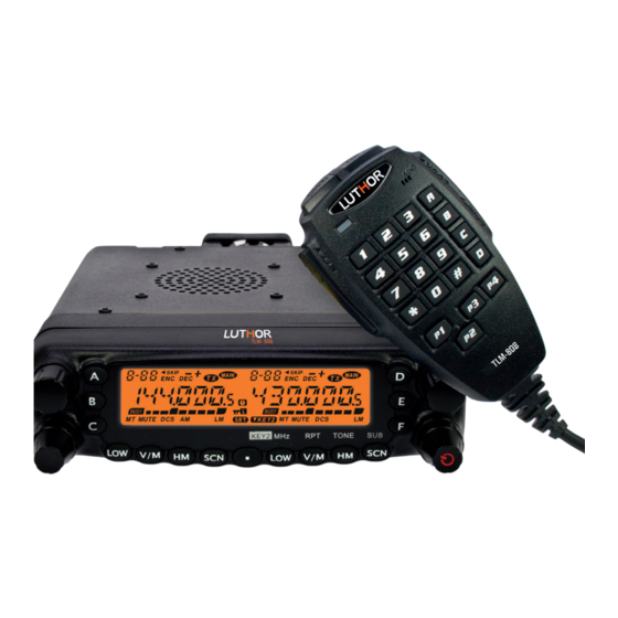
- Page 1 TLM-808 USER’S MANUAL DUAL BAND MOBILE TRANSCEIVER VHF / UHF...
- Page 2 We want to appreciate the confidence shown by purchasing this dual band transceiver LUTHOR TECHNOLOGIES model TLM-808. This transceiver offers an innovative design in terms of technology and multi-functionality. Its high quality and extensive features make it one of the best equipments in its field, we trust in your total...
- Page 3 Please read carefully the following manual before using the transceiver in order to guarantee the equipment’s maximum performances. The use of the symbol shows that this equipment it’s under use restrictions in certain countries. Countries where the use of this equipment is permitted, without prejudice that in any of them their administration request a licence, an authorisation or indicates some restrictions.
-
Page 4: Cautions And Practical Advices
Cautions and practical advices • Do not use the transceiver if you are driving a vehicle. To prevent accidents, focus only on driving. • This transceiver is designed for a power supply maximum voltage of 13,8 volts. Do not use a battery with 24 volts to supply power to the transceiver. •... -
Page 5: Table Of Contents
Contents index Included in the package ..........................9 Main features ..............................10 Installation .................................11 Mobile transceiver installation ......................11 Mounting bracket installation ......................12 Controller cable connection .........................12 DC Power cable connection .........................14 Base station installation ........................16 Fuse replacement ............................18 Antenna connection ..........................19 Accessories connection ..........................20 Microphone ..............................22 Transceiver’s description ..........................23 Front panel ..............................23... - Page 6 Basic functions ...............................32 Power on / off the transceiver......................32 Setting the volume ...........................32 Setting the squelch level ........................32 Selecting the operating band ......................33 Selecting the frequencies band ......................34 Setting a frequency ..........................34 Receiving a call ............................35 Transmitting a call.............................35 Setting the transmission power level ..................36 Memory functions .............................37 Storing memory channels ........................37 Separate Transmit Frequency Memory (“Odd Splits”) ............39...
- Page 7 Memory only mode ...........................43 Advanced functions .............................44 Repeater operation ..........................44 CTCSS tones / DCS codes operation ....................46 DCS codes inversion ...........................49 CTCSS / DCS search scanning .......................50 User-defined CTCSS tones / DCS codes ..................51 Searching .................................53 Time ................................53 Busy ................................53 VFO search ...............................54 Memories search ..........................54 Memory skip search ...........................55...
- Page 8 DTMF operation............................60 2-tones and 5-tones signals operation ..................62 ARTS operation ............................63 Cross-band repeater operation ......................66 Assignment of microphone keys .....................67 Function’s detailed descriptions ......................70 Reset procedure .............................86 Troubleshooting guide..........................87 Technical specifications ..........................88 Note on evironmental protection .......................90 Declaration of conformity ........................91...
-
Page 9: Included In The Package
Included in the package 1 x Radio transceiver 1 x Microphone with DTMF keyboard 1 x Mobile mounting bracket 1 x DC power cord with fuse 1 x Controller cable 1 x Front panel mounting bracket 1 x Set of screws 1 x Protection fuse 1 x User’s manual... -
Page 10: Main Features
Main features Covers 2 transmitting bands: 144 / 430 MHz Wide reception bands for AM and FM: 108-180MHz, 134-174MHz, 350-520MHz Independent controls for both left and right bands V+U simultaneous reception capability Built-in V+U cross-band repeater and full duplex capability 800 memory channels with independent settings 50W high power output in VHF band and 40W in UHF band 50 CTCSS tone groups and 104 DCS digital tone groups... -
Page 11: Installation
Installation Mobile transceiver installation To install the transceiver, look for a suitable and secure location inside your vehicle to reduce the risks for the passengers and yourself while the vehicle is in movement. Consider to install the station in an appropriate position so that your knees and your legs will not be able to hit it during a sudden braking manoeuvre of your vehicle. -
Page 12: Mounting Bracket Installation
2. Insert the supplied screws with its nut and washer, and tighten them. 3. Adjust the most appropriate angle according to its position. Controller cable connection With your TLM-808 a 4,5m controller cable is supplied. Connect the front panel and the main unit using the controller cable as shown below. - Page 13 Main unit Front panel...
-
Page 14: Dc Power Cable Connection
DC Power cable connection Note: install the connector for power supply as close as possible to the transceiver. The vehicle’s battery must be a 12 volts battery. Never connect the transceiver to a 24 volts battery. Make sure to use a 12 volts vehicle battery which has enough power capacity. - Page 15 the battery terminals; the red cable must be connected to the positive (+) terminal, and the black cable must be connected to the negative (-) terminal. 4. Connect again the negative (-) cable from the battery. 5. Connect the supplied power cable to the transceiver’s power connector. Press firmly the connectors until the locking flanges snap.
-
Page 16: Base Station Installation
Base station installation A 13,8V DC power supply (optional, not supplied) is required for operating this trans- ceiver as a base station. Please, contact your dealer. The current recommended for the power supply is 12A. 1. Connect the power cord to the output terminals on the power supply and make sure the polarity is right. - Page 17 Switching power supply Black Switching power supply Power cord with fuse...
-
Page 18: Fuse Replacement
Fuse replacement If a fuse has blown, determine the cause, and then correct the problem. After solving the problem, replace the fuse. If the new installed fuse blows, disconnect the power cord and contact your dealer or an authorised technical service. Fuse location Fuse amperage Transceiver... -
Page 19: Antenna Connection
Use only fuses of the same type and amperage specified, in any other case the transceiver could be damaged. Note: if you use the transceiver during a long period of time when the vehicle’s bat- tery is not fully charged, or when the engine is off, the battery could fully discharge, and maybe will not have enough reserve to start the vehicle. -
Page 20: Accessories Connection
tors and other electronic equipments. Note: transmitting without connecting any antenna or another equivalent charge can damage the transceiver. Always connect the antenna to the transceiver before transmitting. All the base stations should be equipped with a lightning conductor to reduce the risk of fire, electrical discharge and damages on the transceiver. - Page 21 Note: the external speaker take the double BTL port, please, value the connection method. The speaker can not connect with the ground connection, otherwise the speaker could be damaged. The connection method showed below is wrong. Error Grounding...
-
Page 22: Microphone
Microphone For voice communications, connect a microphone equipped with an 8-pin modular connector on the modular connector located on the front of the station. Press firmly the connectors until the locking flanges snap. Fix the supplied microphone on a proper place using the supplied screws. -
Page 23: Transceiver's Description
Transceiver’s description Front panel FUNCTION 1. Adjusts left band’s dialing. 2. Short-press to adjust left band as the main band. Left Control 3. Short-press to adjust (with 1 MHz steps). 4. Keep pressed during half a second to change left operating band between: 144 MHz ->... - Page 24 1. The external volume control adjusts the speaker audio level for the left receiver. 2. Short-press to activate/deactivate the KEY2 mode. Left SQL / vol. 3. Keep pressed during half a second to lock/unlock the front panel KEY2 keys. 4. The internal Squelch control adjusts the noise level for the left receiver.
- Page 25 1. Short-press to activate the channel’s search for the left band. Left SCN 2. When the left band is adjusted on MR mode, keep pressed during half a second to set the memory skip search or the preferential memory search. 1.
- Page 26 1. Short-press to recall a frequency from your favourite HOME memory. Right HM 2. When the right band is adjusted on VFO or MR modes, keep pressed during half a second to activate the priority channel searching. Right TONE Short-press to change the tone’s squelch mode between: ENC (CTCSS coding), ENC DEC (CTCSS coding and decoding) or DCS.
- Page 27 1. Keep pressed any of this keys during about two seconds to store the radio current configuration in one of the special “Hyper” memory banks. Hyper memory keys 2. Short-press any of this keys to recall the information stored on the desired “Hyper”...
-
Page 28: Introduction To Display's Icons
Introduction to display’s icons Nº Icon Function Memory channel number Preferential memory channel Skip memory channel Negative shift direction Positive shift direction “Odd Splits” CTCSS coding... - Page 29 CTCSS decoding Transmitting Main band Busy channel (or Squelch off) Memory tuning Audio mute DCS digital code AM reception Low power output Medium power output Automatic power off Keyboard lock Menu set Mode 2 key on...
-
Page 30: Back View
Back view Nº Connector Function Connection for a 50Ω antenna. EXT SP Connection for an optional external speaker. DATA Connection for programming via PC. Microphone See information on next page... - Page 31 Nº Function PTT button Press button to transmit. DWN button Tune down the channel number or set value. UP button Tune up the channel number or set value. Talk to this during transmission. LOCK Lock microphone keys except 0-9 and PTT button. LAMP Lights up the microphone keypad.
-
Page 32: Basic Functions
Basic functions Power on/off the transceiver To power on the transceiver, keep pressed the Right during half a second. To power off the transceiver, keep pressed the Right during half a second. Setting the volume Turn the external volume control clockwise to increase the volume, and turn it counter-clockwise to decrease the volume. -
Page 33: Selecting The Operating Band
SQL controls. Selecting the operating band By default, the TLM-808 operates on the dual reception mode. During the operation on dual reception mode, the main frequency band (in which is possible to transmit), is shown through the “... -
Page 34: Selecting The Frequencies Band
Keep pressed the right control during half a second to change right operating band between 144 MHz and 430 MHz. Note: if necessary, the TLM-808 can operate on a V-V or U-U mode V - V o U - U. VHF-VHF Operation (V - V) -
Page 35: Receiving A Call
In the main frequency band, short-press the main control and next turn it to change the main band frequency in 1 MHz frequency steps. This function is useful to make fast sweeps through all the frequency range of your TLM-808. 2. Direct frequency entry through the microphone keypad The keypad of your DTMF microphone can be used to directly introduce the main band frequency. -
Page 36: Setting The Transmission Power Level
Note: while keeping pressed the PTT button, the orange colour of the led indicator and the power strength on the radio display will denote that you are transmitting Setting the transmission power level To change the output power level, press the [LOW] key to select one of the four power settings. -
Page 37: Memory Functions
Memory functions Your TLM-808 provides four kinds of memory systems, which are the following: 800 standard memory channels numbered from 001 to 800. 5 pairs of Band-Edge memories (memories allowing to limit a search between a minimum and a maximum frequencies) labelled from “L1/U1”... - Page 38 4. Keep pressed once again the key during half a second to add an alphanumeric label to the memory. Turn the main band control to select the first character of the name you want to store, short-press the control or the [UP] microphone key to advance to the next character.
-
Page 39: Separate Transmit Frequency Memory ("Odd Splits")
Separate Transmit Frequency Memory (“Odd Splits”) 1. Store the receiving frequency following the steps described above. 2. Change to the desired transmission frequency in main band, next keep pressed the key during half a second. 3. Use the main band control or the [UP] / [DWN] microphone keys to select the same memory number you have used in step 1. -
Page 40: Memory Tuning
desired channel. Memory tuning 1. In MR mode, select the desired channel. 2. Keep pressed the [V/M] key during half a second, the icon will be shown on the display. 3. Turn the control to select a new frequency. The steps you make in the current band for VFO operation will be the steps used during the memory tuning. -
Page 41: Home Memory Channel
HOME memory channel The TLM-808 allows you to quickly recall your favourite operation frequency for each one of the bands, it is called HOME memory channel. 1. In the main band, select the desired frequency as well as the CTCSS tones, DCS codes, frequency shift direction and the output power level in the VFO operating mode. -
Page 42: Hyper Memory Channel
MR mode, press the [HM] key. Hyper memory channel The TLM-808 allows you to store all the radio current configuration settings in a special memory bank called Hyper, including the operating frequency, CTCSS tones, DCS codes, repeater shift, power level, search settings, menu settings, etc. for both left and right bands. -
Page 43: Memory Only Mode
Memory only mode When proceeding to store memory channels, you can set your radio in a Memory only mode, where the operation in VFO mode will not be possible. That can be especially useful during public events, where a substantial number of persons are using the radio for the first time, and you want the maximum simplicity in selecting channels. -
Page 44: Advanced Functions
Advanced functions Repeater operation The TLM-808 provides the useful ARS (Automatic Repeater Shift) function, which automatically applies the suitable repeater shift each time it tunes in the Sub-Bands designed for each repeater. For activating ARS: 1. Short-press the key to enter the menu mode. - Page 45 2. Turn the main control to select menu number 24 (RPT.MOD). 3. Short-press the main band control, next turn the main control to select the repeater shift between “+”, “-” and “OFF”. 4. Short-press the key to store the new setting and return to normal operation mode.
-
Page 46: Ctcss Tones / Dcs Codes Operation
CTCSS tones / DCS codes operation Adjusting the CTCSS tones implies two actions: adjusting the tone mode and adjusting the tone frequency through the menu number 31 (TONE M) and number 30 (TONE F), respectively. 1. Short-press the key to enter the menu mode. 2. - Page 47 7. Short-press the key to store the new setting and return to normal operation mode. 50 groups of Standard CTCSS Tone Frequencies (Hz): As with the CTCSS tones, adjusting the DCS codes require adjusting the tone mode to DCS and next selecting the code. 1.
- Page 48 Note: you can select tone mode (DCS) for the main band through the [P3] microphone key. 4. Once the DCS tone mode selection is completed, short-press the main band control to confirm, next turn the main band control to select menu number 7 (DCS.COD). This menu is used to set the DCS code.
-
Page 49: Dcs Codes Inversion
104 groups of Standard DCS code numbers: DCS codes inversion In those cases where you detect that receiver’s squelch not opening when both of you and another radio are using a common DCS code, you can try the following: 1. Short-press the key to enter the menu mode. -
Page 50: Ctcss / Dcs Search Scanning
TRX N: normal DCS coding and decoding; RX R: normal DCS coding and inverted DCS decoding; TX R: inverted DCS coding and normal DCS decoding; TRX R: inverted DCS coding and decoding; 4. Short-press the key to store the new setting and return to normal operation mode. -
Page 51: User-Defined Ctcss Tones / Dcs Codes
Press the key at any time to stop the search. User-defined CTCSS tones / DCS codes The TLM-808 has the possibility to use user-defined CTCSS tones or DCS codes. For CTCSS tones: 1. Short-press the key to enter the menu mode. - Page 52 2. Turn the main control to select menu number 30 (TONE F), short-press the main band control to enter the setting. 3. Introduce the code number directly through the microphone keypad. The range is between 67.0 and 254.1 Hz. 4. Short-press the key to store the new setting and return to normal operation mode.
-
Page 53: Searching
Searching The TLM-808 allows you to scan both in the memory channels of the whole operating band, and on a section of this band. It will stop in any signal found, that way you will allow to communicate with the radios of that frequency, if you wish it. -
Page 54: Vfo Search
4. Short-press the key to store the new setting and return to normal operation mode. Note: the default setting for resuming the search is “TIME”. VFO search 1. If necessary, select the VFO mode by pressing the [V/M] key. 2. Press the [SCN] key to start the search. 3. -
Page 55: Memory Skip Search
Press the [SCN] key to start the search. In the same way as in mode VFO, when the scanner finds a strong enough signal to open the squelch, the scanner will temporarily stop, and will resume the search according to the selected setting for the search resume. To cancel the search, press the [SCN] key again. -
Page 56: Preferential Memory Search
Preferential memory search You can set a preferential memory search list at which you can call on Memory mode. These channels, once they are set, are designed by the icon. When you select the preferential memory search mode, just the channels designated with the icon will be searched. -
Page 57: Exploring Programmed Memories
4. Short-press the key to store the new setting and return to normal operation mode. 5. Now, press the [SCN] key to start the preferential memory search. Only the channels designated with the icon will be searched. 6. To cancel the preferential memory search, on step 3 select “MEM”. Exploring programmed memories This feature allows you to set Sub-Band limits, whether it is for exploring or manually activating the VFO operation. -
Page 58: Priority Channel Searching (Dual Watch)
If not, it will not be valid. Priority channel searching (Dual Watch) The TLM-808 includes a search function on two channels that allows you to operate on any of the VFO, Memory or Home channel modes, while periodically check the activity on a user-defined priority memory channel. -
Page 59: Memory Priority
3. Keep pressed the [HM] key during half a second to activate the VFO priority mode. The display will remain on the current VFO frequency, but every 5 seconds it will check if there is any activity on priority memory channel. 4. -
Page 60: Dtmf Operation
DTMF operation The TLM-808 has two different methods to initiate the DTMF signalling. 1 - Using the numeric keys on the microphone Keeping pressed the PTT button, introduce directly the telephone number of the other(s) radio(s) through the numeric keys on the microphone: 0-9, *, #, A, B, C, D. - Page 61 telephone number. 4. Short-press the main band control, next turn the main control to select the first digit from the telephone number you want to store. 5. Once you have selected the right digit, press the main band control to confirm. Next turn the main control to select the second from the 16 available digits on the current auto-dialling DTMF memory registry.
-
Page 62: 2-Tones And 5-Tones Signals Operation
To transmit the stored telephone numbers: 1. Short-press the key to enter the menu mode, turn the main control to select the auto-dialling DTMF memory that will be transmitted through menu number 12 (DTMF W). 2. Press the key to store the new setting and return to normal operation mode. 3. -
Page 63: Arts Operation
keys on the microphone. And you can store the auto-dialling memories through the programming software, but you can not make it manually. To transmit the memorized 2 or 5 tones signals: 1. Select the 2-tones memorized channel through menu number 38 (2 TONE) or the 5-tones through menu number 39 (5 TONE). - Page 64 your radio will transmit a signal that will contain during one second the DCS code. If the other radio is inside the range, the locator will sound (if is activated) and the “IN.RNG” message will be shown on the display instead of the out of range “OUT.RNG” message showed when the ARTS operation began.
- Page 65 4. Short-press the main band control, next turn the main control to select the ARTS warning option between: IN.RNG: the warnings are only emitted when the radio first confirms is inside of range, but from then on does not reconfirm with warnings. ALWAYS: each time receiving an exploration transmission from another radio, you will hear the alert warnings.
-
Page 66: Cross-Band Repeater Operation
Cross-band repeater operation The TLM-808 can be set to operate as a cross-band repeater through a simple menu procedure. This is a useful function for emergency works in remote areas, as well as for cross-band connections. Note: 1. Check the rules and regulations of your country to ensure that this kind of operations are permitted. -
Page 67: Assignment Of Microphone Keys
6. Short-press the key to exit the cross-band repeater mode and return to normal operation mode. Assignment of microphone keys The user can assign different functions to the microphone keys of the TLM-808, just... - Page 68 in case you wanted to use any other function in any of these keys. To assign a function to a key: 1. Short-press the key to enter the menu mode. 2. Turn the main control to select any of the menu numbers from 19 to 22 (19 – PG P1, 20 –...
- Page 69 TCALL Enables the 1750 Hz tone for repeaters accessing (with the programming software, you can select between 1000 / 1450 / 1750 / 2100 Hz). RPTR Selection of main band shift direction. Enables main band priosity channel. TONE Enables the CTCSS/DCS main band operation. Enable the 1 MHz main band frequency steps.
-
Page 70: Function's Detailed Descriptions
Function’s detailed descriptions Using the menu 1. Short-press the key to enter the menu mode. 2. Turn the main control to select the menu number you wish to adjust (you can also introduce directly the menu number through the microphone keypad). 3. - Page 71 2.- Automatic Repeater Shift - ARS Function: enables or disables the automatic repeater shift function. Available values: ON / OFF Default value: OFF 3.- ARTS Function: selection of the ARTS warning. Availables values: IN.RNG / ALWAYS IN.RNG: the warnings are only emitted when the radio first confirms is inside of range, but from then on does not reconfirm with warnings.
- Page 72 Default value: BEP.ON 5.- CPU clock frequency - CLK.SFT Function: sets the CPU clock frequency. Availables values: SFT.ON / SFT.OFF Default value: SFT.OFF 6.- DIMMER Function: sets the display brightness levela. Availables values: DIM OFF / DIM 01 / DIM 02 / DIM 03 / DIM 04 Default value: DIM 04 7.- DCS.COD Function: sets the DCS codes.
- Page 73 8.- DCS.N/R Function: sets the normal or inverted DCS codes. Availables values: TRX N / TX R / RX R / TRX R Default value: TRX N 9.- DSP.MOD Function: sets the memory channel display mode. Availables values: DSP.FRQ / DSP.NAM Default value: DSP.FRQ 10.- DTMF D Function: sets the delay time for sending the first DTMF digit.
- Page 74 11.- DTMF S Function: sets the speed for sending the DTMF digits. Availables values: 50 / 75 /100 ms Default value: 50 ms 12.- DTMF W Function: stores the auto-dialling DTMF memories. There are 16 auto-dialling DTMF memories available. 13.- HYPER Function: enables or disables the Hyper memory automatic writing.
- Page 75 Availables values: KEY 1 / KEY 2 Default value: KEY 1 15.- LOCK Function: enables or disables the keyboard lock. Availables values: MANUAL / AUTO Default value: MANUAL 16.- LOCKT Function: enables or disables the PTT button lock. Availables values: OFF / BAND R / BAND L / BOTH Default value: OFF OFF: enables the PTT button.
- Page 76 17.- MUTE Function: sets the audio mute mode. Availables values: OFF / TX / RX y TX/RX 18.- NAME Function: stores an alphanumeric label for a memory channel. 19.- PG P1 Function: programs the P1 key function. Default value: BAND / VFO / MR / OFF / SCAN / SQL OFF / TCALL / RPTR / PRI / LOW / TONE / MHZ / REV /HOME / BAND 20.- PG P2 Function: programs the P2 key function.
- Page 77 21.- PG P3 Function: programs the P3 key function. Default value: TONE / MHZ / REV / HOME / BAND / VFOMR / OFF / SCAN / SQL OFF / TCALL / RPTR / PRI / LOW 22.- PG P4 Function: programs the P4 key function.
- Page 78 24.- RPT.MOD Function: sets the repeater shift direction. Availables values: RPT.OFF / RPT.- / RPT.+ Default value: RPT.OFF 25.- SCAN Function: sets the search resume mode. Availables values: TIME / BUSY Default value: TIME TIME: the scanner will stop in a signal found, and will wait for 5 seconds. If you do not make any action during this period, the scanner will resume the search although the signal remains active.
- Page 79 26.- SCAN MODE Function: sets the memories search mode. Availables values: MEM / MSM Default value: MEM MEM: enables the memory search in all memory channels (except the ones marked to be skipped during the search). MSM: enables the memory search only for preferential channels. 27.- SHIFT Function: sets repeater shift.
- Page 80 Availables values: 2,5 / 5 / 6,25 / 7,5 / 8,33 / 10 / 12,5 / 15 / 20 / 25 / 30 /50 / 100 KHz Default value: 12,5 KHz Note: the frequency steps can be independently set for both left and right bands. 29.- SPK Function: sets the silencing mode (squelch).
- Page 81 / DCS code or the same DTMF / 2TONE / 5TONE signal. *It has to be previously activated to be displayed on the display 30.- TONE F Function: sets the CTCSS tone frequency. Availables values: 50 standard CTCSS tones. Default value: 100 Hz Note: the CTCSS tone can be independently set for both left and right bands.
- Page 82 32.- Time Out Timer - TOT Function: sets the time limit of a continuous transmission. Availables values: OFF / 1... 30 min Default value: 6 min 33.- TALKAR Function: switches to simplex working mode when the radio is out of repeater range or when the repeater is not active.
- Page 83 35.- Cross-band repeater - X-RPT Function: enables or disables the cross-band repeater mode. 36.- AM Function: enables or disables the AM mode. Availables values: ON / OFF Default value: OFF 37.- AUT.AM Function: enables or disables the AM automatic mode. Availables values: AUTO / OFF Default value: AUTO 38.- 2 TONE...
- Page 84 Default value: 2T-01 39.- 5 TONE Function: sets the 5tones auto-dialling to the memory channel. Availables values: 5T-01 … 5T-16 Default value: 5T-01 40.- SCR Function: enables or disables the encryption function. Availables values: ON / OFF / 1 a 8 Default value: OFF 41.- COMP Function: enables or disables the voice compander function.
- Page 85 42.- HSD.TYP Function: sets the 2 TONE / 5 TONE / DTMF silencing. Availables values: OFF / 2 TONE / 5 TONE / DTMF Default value: OFF...
-
Page 86: Reset Procedure
Reset procedure Procedure Power off the radio. Keep pressed the left [LOW] key at the same time you power on the radio. Turn the main control to select the wished option: F-1 SETMOD RESET: restores the menu settings to factory defaults. F-2 HYPER RESET: deletes the hyper memories settings to factory defaults. -
Page 87: Troubleshooting Guide
Troubleshooting guide Problem Possible cause and possible solution The display does not show anything. The positive and negative polarities are changed. Connect the red cable to the positive terminal, and the black cable to the negative terminal of the power supply. The fuse has blown. -
Page 88: Technical Specifications
Technical specifications General LUTHOR TECHNOLOGIES Reference TLM - 808 Frequency range Dualband: TX: 144-146 MHz / 430-440 MHz AM/FM RX: 108-180 MHz / 350-512 MHz Memory channels 809 channels Frequency steps 2.5/5/6.25/7.5/8.33/10/12.5/15/20/25/50/100 Khz Emission mode Antenna impedance 50 Ω Frequency stability ±... - Page 89 Transmitter Output power 50 / 20 / 10 / 5 W (144 MHz) 40 / 20 / 10 / 5 W (430 MHz) Maximum deviation < -60 dB (29 MHz: < -50 dB) Modulation distortion < 3% Microphone impedance 2 kΩ Receiver Sensitivity (12 dB Sinad) <0,2 µV...
-
Page 90: Note On Evironmental Protection
We have done everything possible to obtain the maximum of detail in this manual, but we are not responsible for any possible omission as well as printing or translation mistakes. All the specifications are subject to change by LUTHOR TECHNOLOGIES without previous notice. Note on environmental protection... -
Page 91: Declaration Of Conformity
B66339029 E-mail address: gestiontecnica@genereus.com We declare under our sole responsibility the conformity of the following product: Type of equiment: Dual band mobile transceiver VHF/UHF Brand name: LUTHOR TECHNOLOGIES Model number: TLM-808 Manufacturer: GENEREUS S.L. Manufacturing site: China Which it refers this declaration, with the following rules or other policy documents: - EN 60950-1:2006+A11:2009+A1: Safety regarding information technology equipments. - Page 92 services; Part 1: Common technical requirements; Part 5: Specific conditions for Private land Mobile Radio (PMR) and ancillary equipment (speech and non-speech). - EN 301 783-1 V1.2.1 / Electromagnetic compatibility and Radio spectrum Matters (ERM); Land EN 301 783-2 V1.2.1 Mobile Service;...
- Page 93 Notes...
- Page 94 “LIFE IS GOOD COMMUNICATION” luthortechnologies.com Importador/Imported by Importé par Genereus S.L. ES B66339029...
Need help?
Do you have a question about the TLM-808 and is the answer not in the manual?
Questions and answers