Advertisement
Quick Links
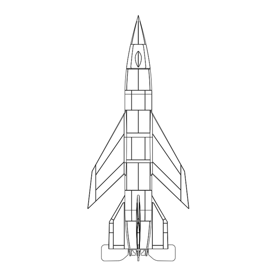
EMW A6
The exceptional increase of range obtained from installing gliding wings in
the A4 (V2) missile induced von Braun to design three crewed variants:
the A4b, piloted as an aerodynamic research aircraft; the A9, as an
intercontinental bomber; and the A6, as a "reconnaissance aircraft at a
high speed and height." Actually, they were scientific research projects of
which the military applications were emphasized to obtain the necessary
resources, considering the wartime circumstances.
The A6 would have been a hypersonic research aircraft, equipped with an
auxiliary engine of ramjet type which could only be started at very high
speeds. This could be possible in this type of airship at the highest point of
its trajectory, flying at a very high speed and with the propellants of the
main rocket exhausted. Under these circumstances, the ramjet engine
(working with synthetic petrol) would give the ramjet the ability to continue
flight for fifteen to twenty minutes without any loss of speed or height. As a
reconnaissance airplane, the A6 would have been impossible to detect.
However, its flying characteristics exceeded the OKL needs and the
project was let down. The A6 was equipped with a pressurized cockpit,
landing gear and braking parachutes. It was vertically launched as an A4
and landed on a conventional landing strip by its own means. The concept
was considered by the Americans during the building and test program for
the North American X-15 research aircraft. Although the content and
purpose of every flight within the X-15 program have not been published,
due to security reasons, there are pictures of one of them with a ramjet
engine installed in the same position as the one chosen by von Braun for
his A6.
A6 Technical Data
Stage: Design
Type: Hypersonic experimental aircraft
Wings: Metallic structure and coating
Fuselage: Metallic structure and coating. It contained, from nose to tail,
the forward landing gear, the pressurized cockpit, the methyl alcohol tank,
the petrol tank (Br-Stoff) for the ramjet, the housing for the main landing
gear, and the payload (instruments, cameras, etc.). Also in the fuselage
were the liquid oxygen tank, the housing for the rocket's mechanisms and
the combustion chamber for the rocket.
Empennages: Metallic structure and coating. For takeoff, they received
some help from the small tailfins installed near the nozzle. It was
necessary to remove the ventral tailfin, used on the A4 and A4b, to be
able to install the ramjet. Landing Gear: Tricycle Power Plant: An EMW
with a thrust of 27,500 kp and an acceleration of up to 6 G, and a ramjet of
unspecified type and thrust.
Source: Luftwaffe 1946 Technical manual.
For building instructions:
https://tinyurl.com/my3d-instruct
EMW A-6
For more model kit updates;
follow us on facebook:
https://tinyurl.com/luft46models
copyright my3dbase 2023
info@my3dbase.com
Advertisement

Related Manuals for my3dbase EMW A-6

Summary of Contents for my3dbase EMW A-6
- Page 1 EMW A-6 EMW A6 The exceptional increase of range obtained from installing gliding wings in the A4 (V2) missile induced von Braun to design three crewed variants: the A4b, piloted as an aerodynamic research aircraft; the A9, as an intercontinental bomber; and the A6, as a "reconnaissance aircraft at a high speed and height."...
- Page 2 Step 3: Bulkhead installation. Step 3: MLG (main landing gear( bay installation. Step 2: MLG bay Step 4: MLG bay rear frame forward frame installation. installation. Step 5: MLG cover installation. Step 4: MLG assembly (repeat for portside). copyright my3dbase 2023 info@my3dbase.com...
- Page 3 Step 1: Engine bracket installation (see placement below). Step 2: Place rocket engine bracket after positioning spar. Install rocket engine flush with after fuselage. Engine bracket Positioning spar Detail B Step 3: RAM engine installtion plus cover and inlet. copyright my3dbase 2023 info@my3dbase.com...
- Page 4 Step 3: Join cockpit section to fuselage and cover with fuselage side shells. Step 6: Nose landing gear installation detail. Step 5: Nose landing gear assembly. Step 7: Attaching aerodynamic control surfaces and rocket guide vanes. copyright my3dbase 2023 info@my3dbase.com...
- Page 5 For gluing, cyanoacrylate glue works well. Warning: Nicht für Kinder unter 6 Jahren geeignet. Erstickungsgefahr durch verschluckbare Kleinteile. Warning: Not suitable for children under 6 years of age. Danger of suffocation due to small parts that can be swallowed. copyright my3dbase 2023 info@my3dbase.com...
Need help?
Do you have a question about the EMW A-6 and is the answer not in the manual?
Questions and answers