
Related Manuals for Pronk Technologies Safe-T Sim ST-1

Summary of Contents for Pronk Technologies Safe-T Sim ST-1
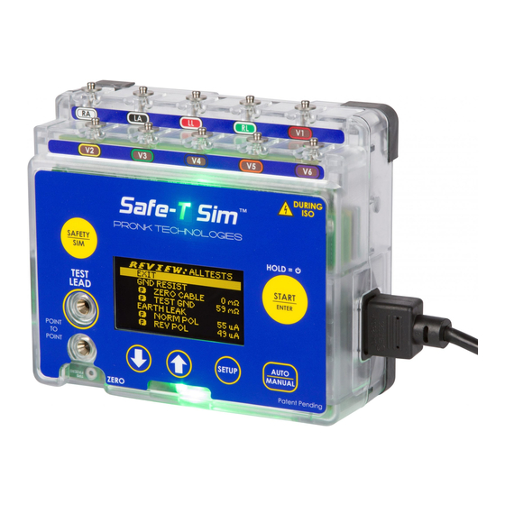
- Page 1 ™ Safe-T Sim ST-1 and ST-1-IEC Electrical Safety Analyzer Operator’s Manual Ph: 800-541-9802 www.pronktech.com Rev. 2020 09-24 SW 2.6 Page 1 of 28...
- Page 2 The device shall only be used with the AC power cord provided or with AA Alkaline or Lithium batteries. Operate this product using only accessories provided by Pronk Technologies. If this equipment is used in a manner not specified by Pronk Technologies, the protection provided by the equipment may be impaired.
-
Page 3: Table Of Contents
Table of Contents Warnings ............................... 4 Safe-T Sim Mobilize Features and Connectivity .................... 5 Front Panel Keys and Connections........................ 6 Introduction .............................. 6 Accessories Included ..........................6 Quick Start: Automated Safety Testing ......................7 Quick Start: Manual Safety Testing ....................... 8 Quick Start: ECG/Respiration Simulation ...................... -
Page 4: Warnings
Contact Information Sales: 800-609-9802 Technical Support: 800-541-9802 FAX: 818-768-5606 Email: sales@pronktech.com Website: www.pronktech.com Warnings To avoid possible electrical shock or personal injury, follow these recommendations: 1. When Lead Leak ISO testing is being performed with the Safe-T Sim Electrical Safety Analyzer, the ECG snaps will have line voltage applied to them. -
Page 5: Safe-T Sim Mobilize Features And Connectivity
Safe-T Sim Mobilize Features and Connectivity Introduction: If your Safe-T Sim has Mobilize, it is capable of being controlled by one of our iOS (and other) Apps via a 2-way wireless Bluetooth connection. Safety testing and simulated values can be controlled by a smart device such as an iPhone or an iPad running a Pronk Mobilize App. -
Page 6: Front Panel Keys And Connections
Profiles and soft key Introduction The Safe-T Sim ST-1 Electrical Safety Analyzer is quick to set up, easy to use and ready to go where you need to be. ST-1 is designed to be used in either Automatic or Manual mode. With Automatic mode, the user can customize up to 5 unique test protocols or “profiles”... -
Page 7: Quick Start: Automated Safety Testing
Quick Start: Automated Safety Testing AUTO mode can substantially speed up Safety Testing. Five factory default automated Test Profiles are preloaded onto ST-1. These profiles are editable by users on the ST-1 directly or via a PC using the USB cable provided (see Cloning Profiles section). -
Page 8: Quick Start: Manual Safety Testing
Quick Start: Manual Safety Testing 1. Press AUTO/MANUAL key, highlight MANUAL, press START 2. MANUAL HOME: Ground Resistance and Leakage testing can be started. Scroll to desired test, press START 3. Manual Testing screen: Ground Resistance Testing shown. Press START again to accept measurement and advance Earth Leakage, or Select EXIT TESTING to return to MANUAL HOME. -
Page 9: Quick Start: Ecg/Respiration Simulation
Quick Start: ECG/Respiration Simulation 1. Press SAFETY/SIM key 2. ECG Heart Rate is highlighted- press START to edit value (ECG HR flashes) OR 3. Down arrow to Resp Rate, press START to edit value (Resp Rate flashes) OR 4. Down arrow to AUTO SEQ, press START to change from Adult, Peds or Neo. Detailed Operation: ST-1 ZERO TEST LEAD: Auto and Manual Mode The ZERO TEST LEAD function calibrates out the resistance of the Test Lead cable. -
Page 10: Electrical Safety Testing: Auto Mode
Electrical Safety Testing: AUTO MODE Insert the DUT power cord into the DUT outlet located on the left side of the ST-1. Connect the banana plug connector of Test Lead to upper test lead jack and the clamp side of test lead to the DUT chassis / enclosure ground lug or exposed metal, if available. -
Page 11: Electrical Safety Testing: Manual Mode
Electrical Safety Testing: MANUAL MODE 1. Insert the DUT power cord into the DUT outlet located on the left side of the ST-1. ZERO TEST LEAD cable, if prompted. Connect the banana plug connector of Test Lead upper test lead jack and the clamp side of test lead to the DUT chassis / enclosure ground lug or exposed metal, if available. -
Page 12: High Current Testing
2. FLOATING GND: If very high resistance is detected between ST-1 and protective earth at Mains, a FLOATING GND message is displayed at the bottom of the screen. When the user presses START, the following warning message is displayed: NOTE: If you are using the ST-1 in an isolated power environment that is causing this message and are confident it will not affect accuracy of electrical safety measurements, select CONTINUE to begin testing. - Page 13 High Current Testing Time Available 2. Once high current draw time limit is reached, the DUT power is removed and the following message will be displayed. ST-1 tracks the time of High Current testing and a timer will be displayed incrementing from zero seconds to show how much time is available for additional High Current tests.
-
Page 14: Electrical Safety Tests Available
Electrical Safety Tests Available Name Definition Zero Test Lead Function to zero out resistance from Test Lead Cable. Resistance measured from the DUT Protective Earth (PE) pin to line GND Resistance PE and/or from Test Lead connected to DUT enclosure to Line PE. Displays leakage current measured through DUT ground line under Earth Leak user selectable fault conditions. -
Page 15: Chassis Leak Tests
CHASSIS LEAK TESTS When initiated, a measurement is displayed of the leakage current between the DUT Chassis / enclosure via the test lead to Protective Earth with a 1000 ohm load in series with the measurement. Test conditions are user configurable including programming test on/off and pass/fail limits as described below. -
Page 16: Point To Point Testing (Hardwired Devices)
Point to Point Testing (Hardwired Devices) Allows Measurement of resistance or leakage between two points (PTP). Black Test Lead Cable required P#: 501-9924. Press AUTO/MANUAL key, highlight POINT TO POINT TESTS, press START. 1. Point-Point Resistance Test a. First time you select PTP Resistance, it is recommended to use the ZERO LEADS function to null resistance of test leads before taking measurement. -
Page 17: Applied Parts- Lead To Lead And Lead To Ground Testing
Applied Parts- Lead to Lead and Lead to Ground Testing NFPA-99 2012 does not call for lead to lead or individual lead to ground testing, however, these tests can be performed using the ST-1, if required. For lead to lead testing, connect a Test Lead to the upper jack of the TEST LEADS jacks. -
Page 18: Customizing Auto Profiles: Detailed
Customizing Auto Profiles: Detailed Users can configure ST-1 based on their testing requirements and preferences. All tests can be configured On or Off and limits can be customized. Safe-T Sim AUTO mode Customization: 1. Press SETUP key, highlight EDIT PROFILE, then START. 2. - Page 19 4. Press START to advance to EDIT: EARTH LEAK tests. Use UP/DOWN arrow keys to highlight value to be edited. Press START to edit value. When Limit value is flashing, use UP/DOWN arrow keys to change value. Press start again to accept edited value.
-
Page 20: Global Settings
Global Settings The following features are global settings, meaning they influence both Manual and Auto modes. They are found in the SETUP page. Setup Menu Name Definition EDIT Users can edit the (5) Auto Profiles. Customize tests ON/OFF, Pass / Fail PROFILE Limits and other features within the Auto Profile. -
Page 21: Cloning Profiles From One St-1 To Others
IMPORTANT: If the password feature is configured ON in the profiles.csv file and the calibration has expired on the unit, a message will be displayed for 5 seconds stating CALIBRATION EXPIRED and the unit will then power off. Unit should be sent in for calibration. The Calibration Cycle (CalMonths) of the ST-1 is user programmable from 6-36 months. - Page 22 customized. The first 29 characters are displayed on initial boot up of the ST-1. Use this for naming your own custom profiles (e.g. “General Hospital Profile 7- 12-2017”. “NFPA99-2012v2.0” (factory Default) Row 3: Global Settings. Every pair of cells is used and its tag to the left specifies its meaning with ranges in parenthesis.
- Page 23 OpenNeutralOpen Row 16 NormPol:LeadLeakageGND Ground Row 17 NormPol:LeadLeakageISO NormalConditions Row 18 NormPol:LeadLeakageISO OpenNeutral Row 19 RevPol:EarthLeakage NormalConditions Row 20 RevPol:EarthLeakage OpenNeutral Row 21 RevPol:ChassisLeakage NormalConditions Row 22 RevPol:ChassisLeakage OpenGround Row 23 RevPol:ChassisLeakage OpenNeutral OpenNeutralOpen Row 24 RevPol:ChassisLeakage Ground Row 25 RevPol:LeadLeakageGND NormalConditions Row 26 RevPol:LeadLeakageGND OpenGround...
- Page 24 DUTon/off/Repeat: Configure ON/OFF. When ON, will prompt user at end of electrical safety tests performed to change state of DUT from on/off or vice versa, then ST-1 will repeat all leakage tests a second time. DUTpwrAtEnd: Configure ON/OFF. When ON, at end of electrical safety tests performed, power at DUT outlet on the Safe-T Sim will be ON.
-
Page 25: Glossary Of Terms
Glossary of Terms Name Definition SAFETY / SIM Key to switch between electrical safety testing and simulation modes. START / ENTER Key to start individual test in manual mode or a series of tests in auto mode. Press and HOLD for 4+ seconds to turn off ST-1. Press again to turn back on. SETUP Key to configure the way ST-1 functions during testing, including beeps, flashing LED, ground resistance limit and more. -
Page 26: St-1 Troubleshooting Tips
ST-1 Troubleshooting Tips ERROR MESSAGE CAUSE WHEN CAN IT OCCUR HOW TO FIX DUT CURRENT DRAW > When a test is running. 1. Remove the DUT from the SAFE-T. 2. Click START to return to main 20 Amps screen. a ER R O R DUT CURRENT DRAW >... -
Page 27: St-1 Limited Warranty
If any fault develops, notify Pronk Technologies (see Returns and Repairs, below) giving full details of the difficulty, and include the model and serial number of the device. -
Page 28: Standards Compliance
7 to 14 business days of our receiving your return. Returns and Repairs Please call Pronk Technologies’ Service Department at 800-541-9802 to obtain a Return Merchandise Authorization (RMA) number and the shipping address. Returns should be packaged securely in the original packaging materials. The RMA number should be clearly marked on the packaging.
Need help?
Do you have a question about the Safe-T Sim ST-1 and is the answer not in the manual?
Questions and answers