
Related Manuals for SUNFLX HSI 3000R


Summary of Contents for SUNFLX HSI 3000R
- Page 1 Solar Storage Inverter User Manual Product Model HSI 3000R Solar storage inverter V1.2...
-
Page 2: Important Safety Instruction
Important Safety Instruction Please keep this manual for future use. This manual contains all safety, installation and operating instructions for HSI 3000R solar storage inverter. Please read all instructions and precautions in the manual carefully before installation and use. Non-safety voltage exists inside the solar storage inverter. To avoid personal injury, users shall not disassemble the solar storage inverter themselves. -
Page 3: Table Of Contents
Contents 1. Basic Information ..............................4 1.1 Product overview and characteristics .......................... 4 1.2 Basic system introduction ...............................5 1.3 Appearance ..................................6 1.4 Dimension drawing ................................7 2. Installation Instruction ............................. 8 2.1 Installation Precautions ..............................8 2.2 Wiring specifications and circuit breaker selection ....................9 2.3 Installation and Wiring .............................. -
Page 4: Basic Information
1.1 Product overview and characteristics HSI 3000R is a new solar storage inverter, which integrates solar energy storage & mains charging energy storage and AC sine wave output. Thanks to DSP control and advanced control algorithm, it has high response speed, high reliability and high industrial standard. -
Page 5: Basic System Introduction
1.2 Basic system introduction The figure below shows the system application scenario of this product. A complete system includes the following parts: 1. PV module: convert the light energy into direct current energy and then charge the battery via the machine, or directly invert the light energy into alternating current to supply power to the load. -
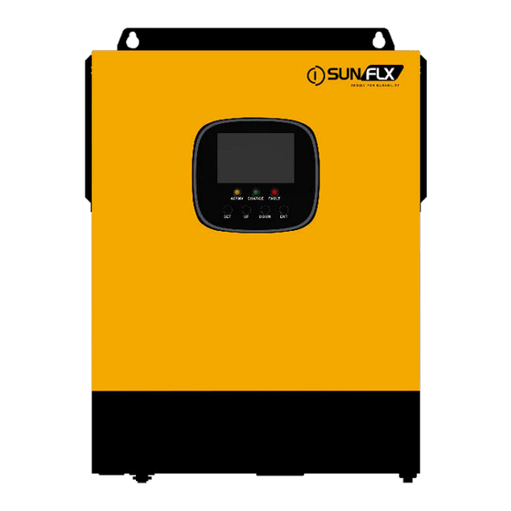
Page 6: Appearance
1.3 Appearance ⑨ AC input terminal Battery input terminal ② ⑩ AC output terminal ON/OFF rocker switch ③ ⑪ USB communication port PV input terminal ④ ⑫ RS485 communication port CAN communication port ⑤ ⑬ Dry contact port Touchable buttons ⑥... -
Page 7: Dimension Drawing
1.4 Dimension drawing Solar storage inverter V1.2... -
Page 8: Installation Instruction
2. Installation Instruction 2.1 Installation Precautions Before installation, please carefully read the manual and get familiar with the installation steps. Be very careful when installing the battery. Wear safety goggles when installing a lead-acid liquid battery. Once coming into contact with the battery acid, rinse with clean water timely. ... -
Page 9: Wiring Specifications And Circuit Breaker Selection
Recommended air switch Model diameter current or circuit breaker type HSI 3000R /8AWG 2P—63A Note: the voltage in parallel shall not exceed maximum PV open-circuit voltage. Refer to the table below for recommended AC input wire diameter and switch: ... -
Page 10: Installation And Wiring
2.3 Installation and Wiring Installation steps: Step 1: confirm the installation position and heat dissipation space, confirm the installation position of machine, such as wall surface; to install the machine, guarantee there is sufficient air flowing through the cooling fins of machine. - Page 11 Step 2: Remove the terminal protection cover Step 3: Wiring Solar storage inverter V1.2...
- Page 12 AC input/output wiring method: Before AC input/output wiring, disconnect the external breaker at first and then confirm whether the cable used is thick enough. Please refer to chapter“ 2.2 Wiring Specification and Breaker type”; Correctly connect AC input wire in accordance with cable sequence and terminal position shown in the figure below.
- Page 13 ① Prior to wiring, disconnect the external circuit breaker and confirm that the wire used is thick enough. Please refer to Section 2.2“Wiring Specifications and Circuit Breaker Selection”. ② Properly connect the PV input wire according to the wire sequence and terminal position shown in the figure below.
- Page 14 Warning notice: Input from mains supply, AC output and PV array may generate high voltage. Before wiring, make sure to break the breaker or fuse; During wiring process, make sure to pay attention to the safety; during the wiring process, please don’t close the breaker or fuse.
-
Page 15: Operating Mode
3.Operating Mode 3.1 Charge mode 1) PV priority: PV module will charge the battery preferentially, and the battery is charged by the Mains only when the PV system fails. During the day, solar energy is fully used to charge, while at night, it converts to the Mains. This can maintain battery level, and is ideal for areas where the grid is relatively stable and electricity price is relatively high. -
Page 16: Output Mode
3.2 Output mode PV priority mode: When photovoltaic is ineffective, it switches to mains power and charging. This mode maximises the use of solar energy while maintaining battery power, and is suitable for areas with relatively stable power grids. Mains priority mode: ... -
Page 17: Lcd Screen Operating Instructions
4. LCD screen operating instructions 4.1 Operation and display panel The operation and display panel is as shown below, including 1 LCD screen, 3 indicators and 4 operation buttons. 4.2 Introduction to operation keys Function Key Description Enter/exit setting menu Last option DOWN Next option... -
Page 18: Introduction To Lcd Screen
4.4 Introduction to LCD screen Icon Function Icon Function Indicating that AC input end Indicating that inverter circuit is in has been connected to working. power grid Indicates that the AC input Indicating that the machine is in mode in APL mode (wide mains supply bypass work mode voltage range) Indicating that PV input end... - Page 19 Indicating that present Indicating that buzzer is not battery type of the machine is enabled lithium battery Indicating that current Indicating alarm of machine battery type of machine is lead-acid battery Indicating that the battery is in Indicating that the machine is in charge state.
- Page 20 Real-time data view method In LCD main screen, press keys “UP” and “DOWN” to turn page and view different realtime data of the machine. Parameters in the Parameters on the right side of the Page Parameters on the left side of the screen middle of the screen screen INPUT BATT V...
-
Page 21: Setting Parameter
4.5 Setting parameter Key operation description: to enter setting menu and exit from setting menu, please press key“SET”. After entering the setting menu, parameter number 【 00 】 shall flash. At this time, press keys “ UP ” and “ DOWN ” to select the parameter item code to be set. Afterwards, press key“ ENT” to enter parameter editing state. - Page 22 When parameter【01】= SBU, the battery voltage is lower than the set value, the output Battery to [04] 43.6V is switched to mains from battery. The setting range mains default is 40V~57.2V. (The maximum value of this item cannot be set higher than item [05].) When parameter【01】= SBU, battery voltage is Mains to [05] 57.6V...
- Page 23 Flooded lead-acid battery, constant voltage [08] FLd charge voltage is 58.4V and float charge voltage is 55.2V. Gel lead-acid battery, constant voltage [08] GEL charge voltage is 56.8V and float charge default voltage is 55.2V. Lithium iron phosphate battery L14/L15/L16 corresponds to lithium iron phosphate battery 14, 15, 16 strings.
- Page 24 When the battery voltage is lower than the Over-discharging [12] 42V judgement point, after delaying for the parameter voltage default 【13】setting time, turn off the inverter output. 40V~48V voltage setting range at 0.4V step. When the battery voltage is lower than parameter Over-discharging [13] 5S 【12】, the inverter output is turned off after...
- Page 25 5min~900min setting range at 5min step. Valid Equalized [19] 240 when battery type is flooded lead-acid batteries, charging delay default sealed lead-acid batteries and user-defined. 0~30days setting range at 1-day step. Valid when Equalized [20] 30 battery type is flooded lead-acid batteries, sealed charging interval default lead-acid batteries and user-defined.
- Page 26 When automatic restart after over-temperature [24] ENA is enabled, If an over-temperature occurs to turn off default the output, it will restart to turn on the output when the temperature drops. [25] DIS Disable alarm. Buzzer alarm [25] ENA Enable alarm. default Disable alarm, when the state of the main input [26] DIS...
- Page 27 [32] SLA default RS485 port for PC and remote monitoring protocol. RS485 [32] BMS RS485 port for BMS communication. communication [32] CAN CAN port for CAN communication. (customized) When [32] setting item = BMS, you need to select the corresponding lithium battery manufacturer's brand for communication.
- Page 28 This mode only takes effect when the inverter communicates successfully with the lithium battery BMS (Battery Management System), and the following options can be set: [SET] When this option is selected, the inverter charging current adopts the value set in item [07], in which case item [07] can be set to any value from 0 to the maximum charging current.
- Page 29 Discharge stops when the capacity is less than this Stop discharging [59] 5% default setting value. (Valid when BMS communication is SOC setting normal) When the capacity is greater than this setting value, Stop charging SOC [60] 100% default charging stops. (Valid when BMS communication is setting normal) When the capacity is less than this setting value,...
-
Page 30: Battery Type Parameters
Battery type parameters For Lead-acid Battery : Battery type Sealed lead Gel lead Flooded lead User-defined acid battery acid battery acid battery Adjustable (USE) Parameters (SLD) (GEL) (FLD) Overvoltage disconnection voltage Battery fully charged recovery point(setup √ item [37]) Equalizing charge 58.4V 59.2V 40~60V... - Page 31 For Lithium Battery : Battery type Ternary Ternary LFP (L16) Adjustable (N13) (N14) (L15) (L14) Parameters Overvoltage disconnection voltage Battery fully charged recovery point(setup 50.4V 54.8V 53.6V 50.4V 47.6V √ item [37]) Equalizing charge √ voltage Boost charge voltage 53.2V 57.6V 56.8V 53.2V...
-
Page 32: Other Function
5.Other Function 5.1 Dry contact Working principle: this dry node can control the switch of diesel generator to charge the battery. ① Under normal conditions, in this terminal, NC-N point is closed and NO-N point is opened; ② when the battery voltage reaches the low-voltage disconnection voltage point, the coil of the relay is energized and NO-N point is closed and NC-N point opened. -
Page 33: Protection
6.Protection 6.1 Protection function Protection Note Function PV current/power limiting When the charge current of the configured PV array exceeds the protection rated current of PV, it will be charged at the rated current. At night, because the battery voltage is greater than that of the PV Anti-reverse charge module, the battery shall be protected against discharge through protection at night... -
Page 34: Meaning Of Fault Code
Bypass overcurrent Built-in AC input overcurrent protection breaker. protection 6.2 Meaning of fault code Affecting Fault Code Fault Name Note output or not 【01】 BatVoltLow Battery under-voltage alarm Battery discharge average current over-current 【02】 BatOverCurrSw software protection 【03】 BatOpen Battery not connected alarm 【04】... - Page 35 【20】 OverTemperInv Inverter heat sink over-temperature protection 【21】 FanFail Fan fault 【22】 EEPROM Memory fault 【23】 ModelNumErr Inaccurate model setting 【26】 RlyShort Inverted AC output backfills to bypass AC input 【29】 Bus under-voltage protection BusVoltLow Battery capacity below 10% alarm (valid when 【30】...
-
Page 36: Some Fault Troubleshooting
6.3 Some fault troubleshooting Fault Solving Measures Check whether the battery air switch or PV air switch is closed; No display on screen whether the switch is in "on" state; press any key on the screen to exit from the screen sleep mode. Charge battery overvoltage... -
Page 37: System Maintenance
7.System Maintenance In order to maintain the best long-term performance, it is recommended to conduct following checks twice a year. Confirm that the air flow around the machine will not be blocked. In addition, remove any dirt or debris from the radiator. -
Page 38: Technical Parameter
8. Technical Parameter Model HSI 3000R AC mode Rated input voltage 220/230Vac (170Vac~280Vac) ±2% Input voltage range (90Vac-280Vac) ±2% Frequency 50Hz/ 60Hz (auto-detect) 47±0.3Hz ~ 55±0.3Hz (50Hz); Frequency range 57±0.3Hz ~ 65±0.3Hz (60Hz); Overload/short- circuit protection Breaker Efficiency >95% Conversion time... - Page 39 Power saving mode Load ≤50W AC charging Battery type Lead acid or lithium battery Maximum charge current Charge current error ± 5Adc Charge voltage range 40–60Vdc Short-circuit protection Breaker and blown fuse Breaker specification Overcharge protection Alarm, stop charging after 1 minute PV charging Max.
- Page 40 Solar storage inverter V1.2...
Need help?
Do you have a question about the HSI 3000R and is the answer not in the manual?
Questions and answers