
Related Manuals for DwyerOmega ACI Averaging Series


Summary of Contents for DwyerOmega ACI Averaging Series
- Page 1 USER’S GUIDE Averaging Series BACnet / Modbus workaci.com For latest product manuals: workaci.com/resources/resource-library...
- Page 2 CONTACT Automation Components workaci.com/contact-us Telephone: 1-(888) 967-5224 Fax: (608) 831-7407 The information contained in this document is believed to be correct, but ACI accepts no liability for any errors it contains, and reserves the right to alter specifications without notice.
-
Page 3: Table Of Contents
Table of Contents General Information ................4 1.1. Wiring Instructions ................4 1.2. Mounting Instructions ................. 6 BACnet MS/TP and Modbus RTU Interface ........8 Baud Rate Selection ................9 EOL Termination Resistance Selection ..........10 Reset ......................10 LED Information ..................10 Address Selection .................. -
Page 4: General Information
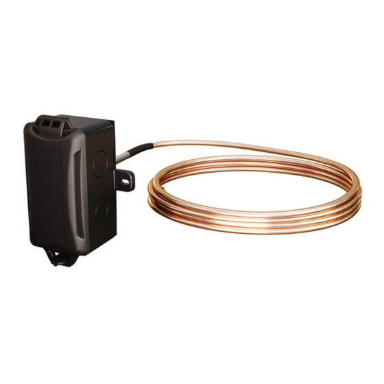
General Information The BACnet MS/TP / Modbus RTU Averaging Series sensor is designed for use with electronic controllers in commercial heating and cooling building management systems. The ACI BACnet MS/TP / Modbus RTU Averaging Series sensor can be ordered to monitor the average temperature in commercial HVAC ductwork and provides a better average temperature of the air inside the duct compared to a single point duct sensor. - Page 5 spikes when de-energizing that can cause malfunction or destruction of electronic circuits. END OF LINE TERMINATION TERMINAL BLOCKS BAC MOD RESET BUTTON Figure 1: Front View Layout Terminal Blocks Connections Power Supply Positive 8 V dc to 34 V dc / 10 V ac to 28 V ac Power Supply Common or Ground EIA-485 Data Negative...
-
Page 6: Mounting Instructions
1.2. Mounting Instructions For optimal temperature measurement, follow these tips: • Mount coil horizontal for vertical stratification. • Mount coil vertical for horizontal stratification. • The sensor must be spread evenly over the full duct. • The entire length of the sensor coil must be installed completely inside the duct. - Page 7 tubing, be careful that you use a gradual bend and that you DO NOT kink the copper tubing. Bends should be a minimum of 50.8 mm (2 in). Each unit includes nylon wire ties and mounts for mounting. Optional copper capillary (ACI Item #130525) or universal plastic mounting clips (ACI Item #145421) can be ordered.
-
Page 8: Bacnet Ms/Tp And Modbus Rtu Interface
HORIZONTAL COILING VERTICAL COILING HANGER STRIPS WIRE TIE MOUNT HANGER STRIPS OPTIONAL COPPER OR PLASTIC CAPILLARY CLIP MIN. BEND RADIUS 2” (50.8 mm) MIN. BEND WIRE TIE MOUNT RADIUS 2” (50.8 mm) OPTIONAL COPPER OR PLASTIC CAPILLARY CLIP Figure 4: Horizontal and Vertical Coiling BACnet MS/TP and Modbus RTU Interface The BACnet Master-Slave/Token-Passing (MS/TP) and Modbus Remote Terminal Unit (RTU) data link protocol uses EIA-485 as a two-... -
Page 9: Baud Rate Selection
set by the controller. This product has auto-baud for ease of network configuration but setting the baud rate using the DIP switches is recommended. Note Auto-baud feature does not function when Modbus is the selected protocol. Baud Rate Selection By default, BACnet Protocol and Auto-Baud is factory set. If the sensor is field adjusted for Modbus RTU, the baud rate should be selected at this time to match the Master configuration. -
Page 10: Eol Termination Resistance Selection
EOL Termination Resistance Selection RS-485 requires that the last device in a chain have a termination resistor. This is controlled using a jumper in the EN (enabled) position marked on Figure 6. When the jumper is set to EN (enabled), a resistance is added in parallel to the data line. -
Page 11: Address Selection
Address Selection Switches 1-7 are used to set the BACnet and Modbus addressing. Refer to Table 3 for switch settings. Each device in a network branch must have a unique address. The value of each position is printed on the board. By default, the address is (0). Note (0) cannot be used if Modbus RTU protocol is selected and will require a unique address. -
Page 12: Device Description
8.5. Device Description By default, the device description is optional but is intended to allow for further information about the device or its environment. The device location can be a character string up to 64 characters in length. 8.6. Temperature Units Configuration For temperature, the units of measure can be configured using BACnet. -
Page 13: Engineering Units
OBJECT OBJECT ID OBJECT RANGE BACnet TYPE NAME ENGINEERING UNITS Device - - - - - - - - BN11x0 0-4194302 - - - - - - - - - degrees- Temperature AI-0 34.7 - 122.0 Fahrenheit (64) Sensor - default Analog Inputs percent-... -
Page 14: Device Configuration Through Modbus Rtu
Device Configuration through Modbus RTU 9.1. Modbus RTU Data Bits, Parity, and Stop Bits Selection Confirm Modbus Protocol is selected via dipswitch #4 on SW4 - see Figure 5. The device that requests information is called the Modbus Master and the devices giving the information are Modbus Slaves. -
Page 15: Modbus Rtu Map
9.4. Modbus RTU Map Reference Address Name Description Coils (CL) 0 = Disable Test Mode. IR3 and IR4 will read with current Sensor Value. 1001 1000 Test Mode Enable 1 = Enable Test Mode. IR3 and IR4 will read with the values stored in HR1001 and HR1002. - Page 16 9007 9006 Non-null terminated character through through Serial Number string of the Serial Number. 9010 9009 For example, “12345678” 9011 9010 Non-null terminated character through through Firmware Version string of the Firmware Version. 9016 9015 For example, “02.00.000.90” Holding Register (HR) Value - Units: Temperature 62 - Degrees Celsius...
-
Page 17: Product Specifications
Device Name, Device Location, and Device Description are 9001 9000 user settable character strings through through Device Name (Null terminated) that can 9016 9015 be used to allow for system customization and device identification. 9017 9016 For example: through through Device Location Device Name (Modbus 9001 9048... -
Page 18: Warranty
WARRANTY The ACI BACnet and Modbus RTU Averaging Series Temperature sensors are covered by ACI’s Five (5) Year Limited Warranty, which is located in the front of ACI’S SENSORS & TRANSMITTERS CATALOG or can be found on ACI’s web site: workaci.com. W.E.E.E. - Page 19 workaci.com I0000932 Improving the world, one measurement at a time. UNIVERSAL FLOW MONITORS...
Need help?
Do you have a question about the ACI Averaging Series and is the answer not in the manual?
Questions and answers