Table of Contents
Advertisement
Quick Links
Advertisement
Table of Contents

Related Manuals for DwyerOmega Dwyer UFM CoolPoint CP Series


Summary of Contents for DwyerOmega Dwyer UFM CoolPoint CP Series
- Page 1 USER’S GUIDE Series CP/CN/CT/CX | CoolPoint® Vortex Shedding Flowmeter Specifications - Installation and Operating Instructions dwyer-inst.com | info@dwyermail.com For latest product manuals: dwyer-inst.com/en/instruction-manuals Bulletin F-CP-CN-CT-CX...
- Page 2 CONTACT Dwyer Instruments, LLC dwyer-inst.com/en/contact-us Toll-Free: 1-800-872-9141 (USA only) Telephone: (219) 879-8000 Fax: (219) 872-9057 Email: info@dwyermail.com The information contained in this document is believed to be correct, but Dwyer accepts no liability for any errors it contains, and reserves the right to alter specifications without notice.
-
Page 3: Table Of Contents
Table of Contents Introduction ..................................4 Specifications ..................................4 Installation ................................... 8 Electrical Connections ..............................8 Operation ..................................... 9 Setup And Configuration ..............................10 6.1. Initial Power Up..................................10 6.2. Model CT ....................................10 6.3. Configuring the solid state relay as alarm output: ....................10 6.4. -
Page 4: Introduction
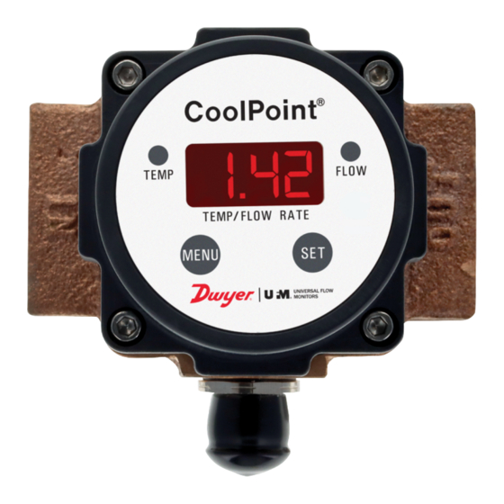
Introduction The Series CP/CN/CT/CX CoolPoint® Vortex Shedding Flowmeter is made for water, water/glycol mixtures, or low viscosity fluids. These units contain no moving parts to clog or wear, allowing for minimal maintenance in the field. This series has two versions: a 3-wire version, where power is supplied separate from the 4 mA to 20 mA output, and a 2-wire loop-powered version. - Page 5 NPT FEMALE CONTROL BOX CAN NPT FEMALE BE ROTATEDTO ANY CONNECTION CONNECTION OF [4] DETENTED POSITIONS IN 90° INCREMENTS OPTIONAL -C2 PIG TAIL CONNECTION CP2, CP3, CP4 CTx (shown with -C2 pig tail connection) 3-1/4 MAX. 5 MAX. [127 MM] [83 MM] CONTROL BOX CAN BE ROTATED TO ANY OF [4] DETENTED...
- Page 6 Model Option A in [mm] B in [mm] C in [mm] D in [mm] E in [mm] F in [mm] G in [mm] H in [mm] 4-3/64 4-59/64 4-3/16 CT2-CT8 4-1/2 [114.3] 2-1/4 [57.15] 3-3/4 [95.25] [102.62] [124.97] [106.43] CT12, 6-3/4 4-23/32 6-9/64...
- Page 7 MAXIMUM LOAD RESISTANCE VS. SUPPLY VOLTAGE 1000 SUFFICIENT INSUFFICIENT 5 10 20 50 100 200 1200 2000 1500 FLOW [LPM] 1000 Ø [OHMS] MODEL CHART Example CP2-M1T1C1-W1 Polysulfone body vortex shedding flowmeter Metal body vortex shedding flowmeter with rotatable display Metal body vortex shedding flowmeter Metal body vortex shedding flowmeter with temperature sensor and Series...
-
Page 8: Installation
Installation For best results, the meters may be installed in any position as long as proper piping installation requirements are observed. This includes sufficient support of adjacent piping to minimize the system’s inherent vibration. Unions of the same pipe size and full port isolation ball valves may be installed for ease of removal and servicing of equipment, if necessary. -
Page 9: Operation
LOAD BROWN 4 mA to 20 mA FLOW SIGNAL OUT WHITE +24 V DC SUPPLY BLUE TEMP RELAY CONTACT PINK 4 mA to 20 mA TEMP SIGNAL OUT TEMP RELAY CONTACT BROWN 4 mA to 20 mA FLOW SIGNAL OUT WHITE +24 V DC SUPPLY GRAY... -
Page 10: Setup And Configuration
Setup And Configuration Factory Default Settings Flow Units: GPM Set Point: 00.0. NO/NC is set to NC. Flow averaging filter set to F 08. Temperature Units: °F 6.1. Initial Power Up Upon supplying the initial DC power, the unit goes into a set-up mode. First, it will energize the LED display, showing that all segments of the display functions (8.8.8. -
Page 11: Alarm Relays And Pulse Output
Step 11: Use the MENU push button to toggle between “nc” and “no”. Step 12: Use the SET push button to store the new relay configuration in memory. 6.4. Alarm Relays and Pulse Output Both CP and CT models can be configured by the user to transmit either a flow alarm signal or a scaled- pulse output. - Page 12 Step 6: Use the MENU button to change the alarm set point, if needed. Note When MENU is pressed once, the display increments to the next value. If the MENU button is held down, the display will initially increment slowly, then increment more quickly until the maximum allowed set point is reached.
-
Page 13: Configuring Response Time In Filter Mode
6.7. Configuring Response Time in Filter Mode: The response time for all models (except E4 or D2) can be configured by the user in the range of 0.9 s to 7.5 s (63 % step response). This is achieved by adjusting the “filtering” array size. Slower response typically provides a more steady output signal, as the instantaneous flow variation (dependent on pump, piping, etc.) is averaged out. -
Page 14: Maintenance/Repair
Maintenance/Repair Upon final installation of the Series CP/CN/CT/CX, no routine maintenance is required. The Series CP/CN/CT/CX is not field serviceable and is not possible to repair the unit. Field repair should not be attempted and may void warranty. Warranty/Return Refer to “Terms and Conditions of Sale” in our catalog and on our website. Contact customer service to receive a Return Materials Authorization (RMA) number before shipping the product back for repair. - Page 15 dwyer-inst.com FR#: 444689-00 Rev. 2 ©Copyright 2024 Dwyer Instruments, LLC Printed in U.S.A. 9/24 Improving the world, one measurement at a time. UNIVERSAL FLOW MONITORS...
Need help?
Do you have a question about the Dwyer UFM CoolPoint CP Series and is the answer not in the manual?
Questions and answers