Table of Contents
Advertisement
Quick Links
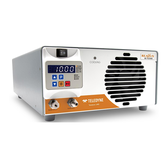
SC-Class
Constant Flow / Constant Pressure
Supercritical Pump
Operator's Manual
903438Rx Rev A
Teledyne SSI
349 N. Science Park Road
State College, PA 16803
www.teledynelabs.com Phone: 814-234-7311
Email:
ssi_sales@teledyne.com.
Use and Disclosure of Data: Information contained herein is classified as EAR99 under the U.S. Export Administration Regulations.
Export, reexport or diversion contrary to U.S. law is prohibited.
Advertisement
Table of Contents

Related Manuals for Teledyne SC-Class


Summary of Contents for Teledyne SC-Class
- Page 1 SC-Class Constant Flow / Constant Pressure Supercritical Pump Operator’s Manual 903438Rx Rev A Teledyne SSI 349 N. Science Park Road State College, PA 16803 www.teledynelabs.com Phone: 814-234-7311 Email: ssi_sales@teledyne.com. Use and Disclosure of Data: Information contained herein is classified as EAR99 under the U.S. Export Administration Regulations.
- Page 2 If water is used to flush or clean the pump, it must be followed with a 100% methanol flush or nitrogen purge, otherwise damage to the pump may occur. SC-Class Pump Operator’s Guide EAR99 Technology Subject to Restrictions Contained on the Cover Page...
-
Page 3: Table Of Contents
INTRODUCTION ............................1 Description of the SC-Class Pump ......................1 1.1.1 Wetted Materials ............................. 1 Specifications for the SC-Class Constant Flow Pump ................2 Specifications for the SC-Class Constant Pressure Pump ............... 3 INSTALLATION ............................4 Unpacking and Inspection ..........................4 Location/Environment .......................... - Page 4 Analog Input Enable ............................... 37 Voltage Input ................................37 Current Input ................................38 Fault Output ................................38 7. WARRANTY STATEMENT ........................... 39 8. COMPANY CONTACT INFORMATION ......................40 SC-Class Pump Operator’s Guide EAR99 Technology Subject to Restrictions Contained on the Cover Page...
-
Page 5: Introduction
The SC-Class constant flow pump is designed to be a reliable component wherever a constant flow must be maintained. The flowrate of the SC-Class pump fitted with two standard 12 mL pump heads can be set in 0.01 mL/min increments from 0.00 to 24.0 mL/min. -
Page 6: Specifications For The Sc-Class Constant Flow Pump
Specifications for the SC-Class Constant Flow Pump Flow Rates 0.01 to 24.00 mL/min Pressure 0 to 10000 psi 2% of full scale pressure Pressure Accuracy Pressure Zero Offset -0 psi +10 psi 2% using 100% methanol @ 1000 psi Flow Accuracy ... -
Page 7: Specifications For The Sc-Class Constant Pressure Pump
Specifications for the SC-Class Constant Pressure Pump Flow Rates 0.01 to 24.00 mL/min Pressure 0 to 10000 psi 2% of full scale pressure Pressure Accuracy Pressure Zero Offset -0 + 10 psi Pressure control Accuracy <10% or 100 psi whichever is larger 5.75”... -
Page 8: Installation
5x20 mm Slo-Blo fuses. Refer to Section 5.8 for instructions on replacing the power entry module fuses. Position the SC-Class pump so that there is at least a 4 inch clearance on all sides of the pump to permit proper ventilation. Plug the pump into a properly grounded electrical outlet using the power cord supplied with the pump. -
Page 9: Instrument Installation
Connect a Carbon Dioxide bone dry grade (99.99% purity) CO tank equipped with a dip tube or siphon tube to the inlet of the SC-Class pump using the adapter shown in Figure 2-4. Note: 1/8" OD PEEK or SS tubing will be required for connection. Length of tubing will be dependent upon specific installation. -
Page 10: Cooler Pre-Run
2" of packaging foam. Although heavy, an HPLC pump is a delicate instrument and must be carefully packaged to withstand the shocks and vibration of shipment. SC-Class Pump Operator’s Guide EAR99 Technology Subject to Restrictions Contained on the Cover Page... -
Page 11: Operation
When the front switch is set to OFF, the front fan will continue to operate until the Heatsink temperature drops below 40° Celsius. Front Panel Controls and Indicators Figure 3-2. Supercritical Pump Front Panel SC-Class Pump Operator’s Guide EAR99 Technology Subject to Restrictions Contained on the Cover Page... -
Page 12: Filter/Inlet And Filter/Outlet
3.2.1 Filter/inlet and Filter/Outlet High-pressure bulkhead filters (2.0 micron rating) are included at the input and output of the SC-Class pump. The Filter/Inlet and Filter/Outlet ports are high-pressure filter closures and are designed for a 1/8" OD tubing connection on the inlet and a 1/16" or 1/8” OD tubing connection on the outlet. - Page 13 Run ..... Lights to indicate the pump is running. FAULT ....Lights when a fault occurs and stops the pump. LEAK ....Not applicable. SC-Class Pump Operator’s Guide EAR99 Technology Subject to Restrictions Contained on the Cover Page...
-
Page 14: Control Panel
Switching back and forth between repeat speeds can be accomplished by pressing and releasing the second arrow button while keeping the first arrow button held down. SC-Class Pump Operator’s Guide EAR99 Technology Subject to Restrictions Contained on the Cover Page... - Page 15 FLOW (flashing) .. When flashing, the display shows the actual flow rate in mL/min. RUN ....When lit, this indicates that the pump is running. FAULT ....Lights when a fault occurs and stops the pump. SC-Class Pump Operator’s Guide EAR99 Technology Subject to Restrictions Contained on the Cover Page...
-
Page 16: Power-Up Configuration
Note that changes will NOT be saved until the RUN/STOP button is pressed; exiting the pump setup menu by turning the instrument power off will discard all changes. SC-Class Pump Operator’s Guide EAR99 Technology Subject to Restrictions Contained on the Cover Page... - Page 17 Leak Detector: The leak detector is not available on the SC-Class model pumps. Analog Input Mode: The next setup parameter displayed is the analog input mode, denoted by the title screen “Input”.
- Page 18 If the firmware is upgraded to a newer version, a non-volatile memory reset will automatically occur the first time the power is switched on. SC-Class Pump Operator’s Guide EAR99 Technology Subject to Restrictions Contained on the Cover Page...
-
Page 19: Rear Panel Remote Input
To avoid nonlethal electric shock when the pump is in operation, avoid touching the areas marked with the high voltage warning symbol. Remove the power cord and turn the pump off before touching these areas. SC-Class Pump Operator’s Guide EAR99 Technology Subject to Restrictions Contained on the Cover Page... -
Page 20: Maintenance
MAINTENANCE Cleaning and minor repairs of the SC-Class pump can be performed as outlined below. Recommended maintenance schedule Item Description Period Inlet/Outlet filter Replace Every 3 months Seals Replace Every 6 months Check Valve Replace Every 6 months Pistons Clean or replace... -
Page 21: Heatsink/Peltier/Pre-Cooler Assembly Removal
(Pull assembly straight forward toward front of cabinet). Note: precooler may stick to heads due to application of thermal grease on precooler face. SC-Class Pump Operator’s Guide EAR99 Technology Subject to Restrictions Contained on the Cover Page... -
Page 22: Changing Pump Heads
4.3.1 Removing the Pump Head Figure 4-2. Pump Head / No-Flush Housing Assembly Note: only one head/no-flush housing shown for clarity. 1. Turn OFF the power to the SC-Class pump. 2. Unplug the power cord. 3. Remove the heatsink/peltier/pre-cooler assembly as described in Section 4.2) -
Page 23: Cleaning The Pump Head Assembly
100% methanol final rinse. Be sure that any moisture and all particles loosened by the above procedures have been removed from the components before re-assembly. SC-Class Pump Operator’s Guide EAR99 Technology Subject to Restrictions Contained on the Cover Page... -
Page 24: Replacing Piston Seals
Each replacement seal kit contains one seal, one backup washer, one no- flush guide bushing, one seal insertion/removal tool, and a pad to clean the piston when changing the seal. SC-Class Pump Operator’s Guide EAR99 Technology Subject to Restrictions Contained on the Cover Page... - Page 25 Orientation is not important in these cases. 3. Place a no-flush guide bushing on the piston. SC-Class Pump Operator’s Guide EAR99 Technology Subject to Restrictions Contained on the Cover Page...
-
Page 26: Changing The Piston
1. Apply a thin, even coating of thermal grease to face of pre-cooler where it mates with the pump heads. Reference Figure 4-1 for orientation of assembly. 2. Slide Heatsink/Peltier/Pre-cooler assembly down between heatsink fan and pump heads. SC-Class Pump Operator’s Guide EAR99 Technology Subject to Restrictions Contained on the Cover Page... -
Page 27: Conditioning New Seals
The assemblies may fall apart, parts may be lost, and they may not operate properly when re- assembled. SC-Class Pump Operator’s Guide EAR99 Technology Subject to Restrictions Contained on the Cover Page... -
Page 28: Cleaning The Pump
Fuse Replacement Three fuses protect the SC-Class pump. Two of the fuses are located in the power entry module at the rear of the cabinet and are in series with the AC input line. The other fuse is located on the motor power circuit board and is in series with the 48 Vdc supply. - Page 29 If the front panel display appears to function normally but the pump motor does not run, check the fuse located on the motor power circuit board. If blown, replace with a 5 A Slo-Blo fuse. SC-Class Pump Operator’s Guide EAR99 Technology Subject to Restrictions Contained on the Cover Page...
-
Page 30: Quick Guide To Problem Solving
1. Contact service technician if problem persists. illuminated, but front fan is not functioning. has failed. Note: front fan is NOT controlled by front never operates. switch. 2. Thermal switch has failed. SC-Class Pump Operator’s Guide EAR99 Technology Subject to Restrictions Contained on the Cover Page... -
Page 31: Rear Panel Serial Communications Port
A computer with appropriate software can be used to control the pump operation remotely via these connections. Additional drivers may be required for utilization of the USB port. The proper driver may be downloaded from Teledyne SSI at https://www.teledynessi.com/support/driver-downloads. Hardware Implementation The RS-232 REMOTE INPUT serial communications port is configured by default for 9600 baud, 8 data bits, 1 stop bit, and no parity. -
Page 32: Pump Command List
OK,GS:<seal>/ Get Seal: returns the seal-life stroke OK,GS:7/ counter value. SC-Class Pump Operator’s Guide EAR99 Technology Subject to Restrictions Contained on the Cover Page... - Page 33 Reset: reset all user adjustable values to factory defaults. This includes the flow rate, upper pressure limit, lower pressure limit, selected solvent, flow rate compensation, and CP values. SC-Class Pump Operator’s Guide EAR99 Technology Subject to Restrictions Contained on the Cover Page...
- Page 34 0850 to 1150 (i.e. ± 15.0%) ZS:OK/ Zero Seal: reset the seal-life stroke ZS:OK/ counter to zero. (no response) Clears all characters from the command buffer. SC-Class Pump Operator’s Guide EAR99 Technology Subject to Restrictions Contained on the Cover Page...
- Page 35 Lower Pressure: stores the lower LPxxxxx pressure limit. psi input format: LP200 = 200 psi bar input format: LP200 = 20.0 bar MPa input format: LP200 = 2.00 SC-Class Pump Operator’s Guide EAR99 Technology Subject to Restrictions Contained on the Cover Page...
- Page 36 0 = override disabled: must connect enable line on external control board to activate analog input. 1 = override enabled: activates analog input regardless of external enable line state. SC-Class Pump Operator’s Guide EAR99 Technology Subject to Restrictions Contained on the Cover Page...
- Page 37 OK,VO:5/ 10V calibration, in A/D counts. VOxxxx OK,VO:<v_offset>/ Voltage Offset: sets offset value used in 0-10V OK,VO:5/ calibration, in A/D counts. input range: 0 to 1000 SC-Class Pump Operator’s Guide EAR99 Technology Subject to Restrictions Contained on the Cover Page...
- Page 38 Proportional Gain: sets the CP algorithm P OK,PG:02000/ term. IGxxxxx OK,IG:<i_gain>/ Integral Gain: sets the CP algorithm I term. OK,IG:00500/ DGxxxxx OK,DG:<d_gain>/ Derivative Gain: sets the CP algorithm D term. OK,DG:0075/ SC-Class Pump Operator’s Guide EAR99 Technology Subject to Restrictions Contained on the Cover Page...
- Page 39 Other bytes cannot be changed. OK,RN/ Reset Network: resets network OK,RN/ settings to default values; also resets user-adjustable values, similar to RE command. SC-Class Pump Operator’s Guide EAR99 Technology Subject to Restrictions Contained on the Cover Page...
-
Page 40: Rear Panel 10-Pin Terminal Board Connector
SC-Class Pump Operator’s Guide EAR99 Technology Subject to Restrictions Contained on the Cover Page... -
Page 41: Run And Stop Inputs
VO and VS commands. To avoid a ground loop, the voltage source should not be connected to the pump ground located on pin 1. SC-Class Pump Operator’s Guide EAR99 Technology Subject to Restrictions Contained on the Cover Page... -
Page 42: Current Input
A TTL level output signal is located on this pin, which identifies whether the pump is operating normally (low signal level) or has faulted (high signal level). SC-Class Pump Operator’s Guide EAR99 Technology Subject to Restrictions Contained on the Cover Page... -
Page 43: Warranty Statement
7. WARRANTY STATEMENT Teledyne SSI (SSI) warrants that instruments or equipment manufactured by the company for a period thirty-six (36) months from date of shipment to the original purchaser (or to the drop ship location as indicated on the Purchase Order from the original purchaser), against defects in materials and workmanship under normal installation, use and maintenance. -
Page 44: Company Contact Information
Teledyne LABS Teledyne SSI 349 Science Park Road State College, PA 16803 800-441-HPLC (4752) Technical Support: 814-234-7311 Sales: Option 2 Technical & Service Support: Option 3 SC-Class Pump Operator’s Guide EAR99 Technology Subject to Restrictions Contained on the Cover Page...
Need help?
Do you have a question about the SC-Class and is the answer not in the manual?
Questions and answers