Table of Contents
Advertisement
Quick Links
Advertisement
Table of Contents

Related Manuals for mac.pan Annular FTUB120


Summary of Contents for mac.pan Annular FTUB120
- Page 1 Annular steam oven FTUB120 – FTUB180 – FTUB240...
-
Page 2: Table Of Contents
CONTENTS 1. Introduction 1.1 Guarantee 1.2 Description of the oven 1.3 Identification of the oven 1.4 Plates and warnings 1.5 Technical data 2. General regulations for safety and accident prevention 2.1 Clothing 2.2 Ecology and pollution 2.3 Safe use 2.4 Safe maintenance _ 3. -
Page 3: Introduction
1. Introduction With this manual manufacturer illustrates the features and technical data, the installation and start up procedure as well as the standard maintenance operations of the ANNULAR STEAM OVEN. In this manual the appliance is generically called the OVEN. This manual also includes the accident prevention measures, the operating diagrams, the transport and unloading operations, the spare parts list and the troubleshooting section. -
Page 4: Description Of The Oven
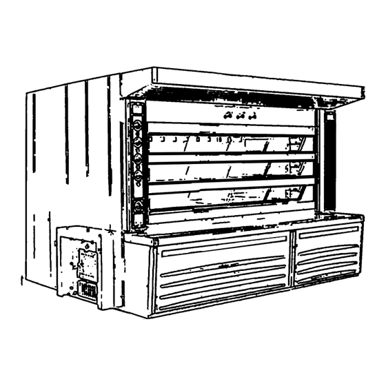
1.2 Description of the OVEN The OVEN consists of baking chambers positioned one on top of the other and heated by electric resistors. It is available in the following models: with 4 doors and with2 to 4 chambers (seetable 1 on page 7). -
Page 5: Plates And Warnings
Figure 2 1.4 Plates and warnings The oven is complete with the manufacturer's plate. Figure 2 illustrates the position where the manufacturer identification plate is normally affixed. The plates have the following meaning (fig. 2): 2) Carefully read the instructions given in this manual before operating the OVEN. 3) Always disconnect from the power supply before carrying out any cleaning or maintenance operation. - Page 6 The characteristics of the OVEN are indicated in the acronym of the model, written on the identification plate (fig. 2). The characteristics of the OVEN shall be identified as follows: FTUB120/4/1L Example: 120 – This code identifies the number of doors per chamber: 120 = No.
- Page 7 OUTER WEIGHT PRODUCTION THERMAL DIMENSIONS CAPACITY INPUT MODEL (mm) (mm) (mm) (Kg) (kg/h) (Kw-Kcal/h) FTUB120/3/1L 1930 2680 2300 5900 52-45000 FTUB120/3/2L 1930 3100 2300 6400 69-60300 FTUB120/3/3L 1930 3310 2300 6800 77-66600 FTUB120/3/4L 1930 3520 2300 7400 85-73800 FTUB120/3/5L 1930 3730 2300 7700...
-
Page 8: General Regulations For Safety And Accident Prevention
FTUB240/3/2L 3170 3100 2300 8800 123-106400 FTUB240/3/3L 3170 3310 2300 9460 137-118400 FTUB240/3/4L 3170 3520 2300 10000 152-131200 FTUB240/3/5L 3170 3730 2300 11000 167-144000 FTUB240/3/6L 3170 3940 2300 11700 181-156000 FTUB240/3/7L 3170 4150 2300 12000 195-168800 FTUB240/4/2L 3170 3100 2300 9400 154-132700 FTUB240/4/3L... -
Page 9: Safe Use
2.3 Safe use It is strictly forbidden to allow anyone who has not read and understood this manual to operate the OVEN. It is strictly forbidden to allow anyone who has not been suitably trained and/or is not competent and/or in good health to operate the OVEN. -
Page 10: Transport And Unloading
3. Transport and unloading. The OVEN is shipped on trucks in loose parts. Use a forklift truck or a crane with a suitable capacity to unload it, making sure that the components are hooked as illustrated here below. When unloading and handling the front section of the oven mouth, it is necessary to be careful and slide the forks of the forklift truck or the ropes of the crane between two chambers;... -
Page 11: Installation
4. Installation. Before starting installation, it is necessary to become familiar with the law provisions and the regulations of the country in which the OVEN will be installed. The room where the OVEN will be installed must have certain characteristics that depend on the fuel used. WARNING IT IS ABSOLUTELY FORBIDDEN TO INSTALL THE OVEN IN ROOMS THAT ARE NOT SUITABLE OR FORESEEN FOR SUCH PURPOSE. -
Page 12: Connection To The Fuel Supply System
4.3 Connection to the fuel supply system. The pipes that connect the burner to the fuel feeding system must be chosen as indicated in table 2. Table 2 BURNER MATERIAL DELIVERY RETURN TYPE: for ovens for ovens ovens ovens ovens up to 12.00 exceeding up to... - Page 13 4.4.1 LIQUID FUEL OVENS Figure 6 Exhaust pipe – Steam piple – Example of a two-conduit chimney The diameter of the chimney used to discharge the smoke depends on the capacity of the oven, according to the following formula, where: K = 0.024 P = Thesum of the power of the fireboxes attached to the chimney, measured in Kcal/h H = The height of the chimney measured in metres, minus:...
-
Page 14: Gas Ovens
Table 3 Annular steam oven 4.4.2 GAS OVENS... -
Page 15: Electrical Connection
The flue pipes must comply with the provisions given hereunder. They must be dimensioned keeping in mind their height, and according to the maximum heat output of the appliances; in any case, their inner section should not be less than what is indicated in table 4. For higher heat outputs, use a diameter of: 3.5 sq. -
Page 16: Using The Oven
The power line must be connected to the hydraulic unit located under the counter (N. 1 fig. 7). The supply pressure must be 3-3.5 BAR. If the network pressure exceeds such values, a pressure regulator must be installed, complete with pressure gauge, which must be calibrated at 3 -3.5 bar. WARNING WHEN THE PRESSURE GAUGE INDICATES A PRESSURE THAT IS LOWER THAN 3 BAR, THE SYSTEM MUST BE FITTED WITH AN AUTOCLAVE. -
Page 17: Starting The Oven For The First Time
5.1 Starting the OVEN for the first time To start the OVEN for the first time, proceed as follows: ° C and ensure that the temperature controller deactivates normally; operate the -set the temperature to °50 OVEN in this conditions for approximately 2 hours; the chimney damper (No. 1 fig. 9) and the steam exhaust valves must be open (No. -
Page 18: Controlling The Steam
WHEN THE OVEN HAS BEEN OFF FOR MORE THAN 24 HOURS, DURING WORKING DAYS IT MUST BE SWITCHED ON 70 MINUTES BEFORE THE FIRST BATCH IS LOADED. 5.2 Controlling the steam To distribute the steam inside the chambers, operate on push-buttons (No. -
Page 19: Oven Operation With Solid Fuel
When using frames to load, refer to fig. 11, which illustrates the relative mechanism. When the frame is released, hook No. 1 must lock into the slot of the mouth in order to slide the belt and drop the product to be baked on the floor of the oven. -
Page 20: Processing On Blue Trays
When the operation is completed, disconnect the main switch (No. 1 fig 8). After 10 or 15 minutes close the chimney damper (NO. 1 fig 9). 5.7 Processing on BLUE trays To prevent the loaves from sticking to the surface of the trays, before using new trays, follow the procedure illustrated here below: 1) degrease and clean the pans with a cloth (even dry) OVEN at about 250°... -
Page 21: Every Week
- EVERY WEEK - Clean the doors. The doors of the chambers can be removed for cleaning purposes. First of all you must unhook the counter to make this operation easier. Then follow the instructions given in fig. 13 to unhook every door. -
Page 22: Occasional Maintenance
- Inner part of the steam generators. Steam generators must be cleaned by removing the screws (No. 6 fig.1 4) and the front flange. 7.2 Occasional maintenance. 7.2.1 REPLACING OVEN LIGHTS To change the bulbs, please do as follows: Use a screwdriver to remove the light cover, (No.1-2 fig. - Page 23 DRAWING DESCRIPTION CODE Two-position - 0-1 luminous selector to SWITCH ON the A900 03 030 panel, the contacts and the LEDs Black push-button complete A900 03 035 with contacts "EVCO" thermostat A900 02 905 24-230V AC – EV9411J6 A900 02 906 "EVCO"...
- Page 24 Length of steam generators' 300 60 260 discharge tube225mm ø ½” 615x50x1 seal for doors' tempered glass A900 01 326 Seal for tempered glass lightlocated inside the A900 01 300 chamber A900 01 514 – 620x300x10 Tempered glass for doors A900 01 504 - 620x320x10 A900 01 515 –...
-
Page 25: Troubleshooting
9. Troubleshooting FAULT POSSIBLE CAUSE REMEDY The oven does not work: no - No power supply. - Find the cause and take the response. - The main switch is not necessary measures correctly positioned. - Correct positioning. - Faulty transformer. - Replace the transformer. - Page 26 Annular steam oven...
- Page 27 STEAM OVEN WITHOUT SIDE FURNACE PLACE N°4 ANGULAR REFRACTORY BRICKS , AND N°2 REFRACTORY PLATE 500x500x80 AS SHOWN IN THE FIGURE YOU HAVE TO USE THE REFRACTORY CEMENT CONTAINED IN THE BIN Annular steam oven...
- Page 28 STEAM OVEN WITHOUT SIDE FURNACE BUILD THE BACK OF THE FURNACE HEIGHT FROM GROUND 425mm YOU HAVE TO USE N°3 REFRACTORY BRICKS 220x110x60 PLACED ON THE GROUND N°6 REFRACTORY BRICKS ( 230x170x100) N° 2 REFRACTORY PLATES ( 500x200x30) VERTICALLY POSITIONED BEHIND THE FURNACE Annular steam oven...
- Page 29 STEAM OVEN WITH SIDE FURNACE PLACE THE ANGULAR REFRACORY BRICKS WITH REFRACORY CEMENT CONTAINED IN THE BIN Annular steam oven...
- Page 30 STEAM OVEN WITH SIDE FURNACE PLACE N°2 REFRACTORY BRICKS 230x170x100 mm WITH REFRACORY CEMENT PLACE N°4 REFRACORY BRICKS 220x110x60 WITH REFRACORY CEMENT Annular steam oven...
- Page 31 STEAM OVEN WITH SIDE FURNACE PLACE N°2 REFRACTORY BRICKS 230x170x100 PLACE N°2 ANGULAR REFRACORY BRICKS PLACE N°1 REFRACTORY PLATE 500x500x80 PLACE N°2 REFRACTORY BRICKS 230x170x100 Annular steam oven...
- Page 32 STEAM OVEN WITH SIDE FURNACE PLACE N°2 REFRACTORY BRICKS 220x110x60 PLACE N°1 CUTTED REFRACORY BRICK 220x80x60 Annular steam oven...
- Page 33 STEAM OVEN WITH SIDE FURNACE PLACE N° 6 REFRACTORY BRICKS 230x170x100 PLEASE NOTE : ALL THE BRICKS MUST BE FIXED WITH REFRACTORY CEMENT Annular steam oven...
- Page 34 STEAM OVEN WITH SIDE FURNACE 160 100 Annular steam oven...
- Page 35 FILL WITH NORMAL CONCRETE UNTIL THE HEIGHT OF THE RECTANGULAR TUBES Annular steam oven...
- Page 36 FILL WITH SAND UNTIL THE HEIGHT OF 20 CM Annular steam oven...
- Page 37 FILL WITH MINERAL ROCK WOOL UNTIL THE HEIGHT OF RECTANGLAR TUBES Annular steam oven...
- Page 38 PLACE THE CORRUGATED METAL SHEETS Annular steam oven...
- Page 39 MAKE A LAYER OF NORMAL CONCRETE UNTIL REACHING THE LEVEL OF FOLDS Annular steam oven...
- Page 40 MAKE A FLAT LAYER WITH REFRACORY PLATES WITH MEASURE 500x200x30 Annular steam oven...
- Page 41 STEAM OVENS MOD. 120 H170 Annular steam oven...
- Page 42 STEAM OVENS MOD. 180 – MOD. 240 – MOD. 300 MODELLO ( A ) ( A1 ) ( B ) ( C ) 310mm 300mm 380mm 560mm 360mm 350mm 640mm 690mm 420mm 380mm 930mm 820mm Annular steam oven...
- Page 43 INSTALL THE BACK PART AND THE CHIMNEY, AND AFTER PLACE THE PERFORATED BACK METAL SHEETS Annular steam oven...
- Page 44 PLEASE NOTE: PLACE THE GLASS FIBER WIRE WITH DIAMETER 3 INSIDE THE FOLD IN ALL THE CHAMBER Annular steam oven...
- Page 45 FIX WITH BOLTS THE BACK PART, THE CHIMNEY AND THE FIRST TUBE SECTOR Annular steam oven...
- Page 46 PLACE 110x220x30 REFRACORY PLATES FILL WITH NORMAL CONCRETE FILL WITH REFRACTORY BETWEEN THE TUBES CONCRETE BETWEEN THE TUBES Annular steam oven...
- Page 47 PLACE N°1 REFRACTORY PLATES 500x200x30 FOR CHIMNEY CLOSURE PLACEN°4 REFRACORY PLATES 500x250x40 FOR CHANNELS CLOSURE Annular steam oven...
- Page 48 PLACE N°2 TUBE SECTORS AND FIX THEM WITH BOLTS FILL WITH REFRACTORY FILL WITH NORMAL CONCRETE CONCRETE BETWEEN THE BETWEEN THE TUBES TUBES Annular steam oven...
- Page 49 PLACE N°2 REFRACORY PLATES 500x200x30 FOR CLOSURE OF FIRST REFRACTORY CHANNEL Annular steam oven...
- Page 50 PLACE THE DIVIDING METAL SHEETS PLEASE REMBER TO PLACE THE GLASS FIBER WIRE Annular steam oven...
- Page 51 STEAM OVEN WITHOUT SIDE FURNACE MAKE A LAYER OF NORMAL CONCRETE UNTIL THE HEIGHT OF THE GRIDS LESS 4 CM 40 mm Annular steam oven...
- Page 52 STEAM OVEN WITHOUT SIDE FURNACE MAKE ONE INCLINED PLANS WITH REFRACTORY PLATES 500x250x40 THAT MUST BE CUT IN LOCAL SITE Annular steam oven...
- Page 53 STEAM OVEN WITH SIDE FURNACE MAKE A LAYER OF NORMAL CONCRETE UNTIL THE HEIGHT OF THE GRIDS LESS 4 CM Annular steam oven...
- Page 54 STEAM OVEN WITH SIDE FURNACE MAKE TWO INCLINED PLANS WITH REFRACTORY PLATES 500x250x40 THAT MUST BE CUT IN LOCAL SITE Annular steam oven...
- Page 55 PLACE N°5 REFRACTORY BRICKS 220x110x60 CUTTED AT 160x110x60 PREPARE THE SUPPORT PLEASE TAKE NOTE THAT THE FIRST PLAN MUST BE POSITIONED SLIGHTLY INCLINED IN REFRACTORY TO INCREASE THE QUANTITY OF HEAT CONCRETE FOR THE BIG IN THE FIRST SECTORS REFRACTORY PLATE PLACE N°2 REFRACORY PLATES 220x110x30...
- Page 56 PLACE THE BIG REFRACTORY PLATE AS SHOWN IN THE PICTURE Annular steam oven...
- Page 57 INSTALL THE FOLLOWING TUBE SECTOR PLACE NORMAL CONCRETE BETWEEN THE TUBES PLACE REFRACTORY CONCRETE BETWEEN THE TUBES PLACEN°2 REFRACTORY PLATES 500x200x30 Annular steam oven...
- Page 58 INSTALL THE LAST TUBE SECTOR PLACE NORMAL CONCRETE PLACE REFRACTORY BETWEEN THE TUBES CONCRETE BETWEEN THE TUBES PLACEN°2 REFRACTORY PLATES 500x200x30 Annular steam oven...
- Page 59 PLACE THE FRONT DIVIDING METAL SHEETS Annular steam oven...
- Page 60 PLACE THE LAST PLACE THE BIG REFRACTORY CUTTED REFRACORY PLATE 600x400x80 PLATE OF FURNACE CLOSING Annular steam oven...
- Page 61 PLACE THE FRONT METAL SHEET FOR FRONT CHANNEL CLOSURE Annular steam oven...
- Page 62 PLACE THE STEAMER AS INDICATED IN THE PICTURE Annular steam oven...
- Page 63 COVER THE OPEN PART OF CHANNELS WITH REFRACORY PLATES 500x200x30 Annular steam oven...
- Page 64 INSTALL THE STEAMER VALVES SILICONE Annular steam oven...
- Page 65 CONNECT WITH FLEX STAINLESS STELL TUBE Ø60, THE STEAMER WITH STEAMER DISCHARGE Annular steam oven...
- Page 66 MAKE A LAYER OF NORMAL CONCRETE UNTIL YOU REACH THE LEVEL OF SIDE BASEMENT PUT HERE A BRICK FOR HELP YOU REACH THE LEVEL OF STEAMER FLANGE Annular steam oven...
- Page 67 INSTALLATION OF OVEN MOUTH, PUT BEFORE THE SILICONE BETWEEN THE MOUTH AND ALL THE PARTS IN CONTACT WITH THE FIRST SILICONE SECTOR OF TUBE Annular steam oven...
- Page 68 FILL WITH NORMAL CONCRETE Annular steam oven...
- Page 69 FILL WITH NORMAL CONCRETE Annular steam oven...
- Page 70 FILL WITH NORMAL CONCRETE PUT HERE THE THERMOSTAT TUBE Annular steam oven...
- Page 71 INSTALL INSIDE THE CHAMBERS THE SIDE COVERS Annular steam oven...
- Page 72 PLACE THE FLOORS IN EACH CHAMBER Annular steam oven...
- Page 73 INSTALL THE FLOOR STOPPER INSIDE EACH CAMBER Annular steam oven...
- Page 74 SILICONE INSTALL THE VALVE BOX Annular steam oven...
- Page 75 PLACE THE SIDE PANNEL SUPPORTS Annular steam oven...
- Page 76 INSTALL THE HAND VALVE SUPORT Annular steam oven...
- Page 77 INSTALL THE ROCK WOOL SIDE COVERS Annular steam oven...
- Page 78 Place N°25 Knurled iron rod for each steamer Annular steam oven...
- Page 79 INSTALL THE STEAMER COVERS Annular steam oven...
- Page 80 INSTALL THE WATER SPRAYER PLEASE NOTE THAT THE SPRAYER HOLES MUST BE FACING DOWN Annular steam oven...
- Page 81 INSTALL THE WATER DISCHARGE Annular steam oven...
- Page 82 PLACE THE TWO CHANNEL CAPS PLACE INSIDE THE CAPS A REFRACTORY BRICK 220x110x60 Annular steam oven...
- Page 83 INSTALL THE TWO COLUMNS WARNING !!! FILL WITH ROCK WOOL THE FREE SPACE. Annular steam oven...
- Page 84 INSTALL THE VALVE RODS AND THE ROD COVERS Annular steam oven...
- Page 85 INSTALL THE FRONT STEAM BOX Annular steam oven...
- Page 86 INSTALL THE PERIMETER BRACKETS Annular steam oven...
- Page 87 INSTALL THE PANEL SUPPORTS Annular steam oven...
- Page 88 BEFORE THE FAN INSTALLATION PUT SILICONE INSTALL THE FAN AS SHOWN IN PICTURE Annular steam oven...
- Page 89 INSTALL THE SAUCTION HOOD Annular steam oven...
- Page 90 PRIMA DI MONTARE IL TUBO FLESSIBILE METTERE IL SILICONE CONNECT THE FLEX TUBE Ø120 BETWEEN THE FRONT AND THE BACK BOX Annular steam oven...
- Page 91 INSTALL THE PANELS AND FILL WITH ROCK WOOL Annular steam oven...
- Page 92 FILL WITH ROCK WOOL Annular steam oven...
- Page 93 FILL WITH RCK WOOL Annular steam oven...
- Page 94 FILL WITH ROCK WOOL Annular steam oven...
- Page 95 FILL WITH ROCK WOOL Annular steam oven...
- Page 96 INSTALL THE OVEN COVERS WARNING !!! BEFORE INSTALL THE COVERS, FILL WITH ROCK WOOL Annular steam oven...
- Page 97 INSTALL THE BENCH Annular steam oven...
- Page 98 Annular steam oven...
- Page 99 Annular steam oven...
- Page 100 Annular steam oven...
- Page 101 Annular steam oven...
- Page 102 Annular steam oven...
- Page 104 www.macpan.com...
Need help?
Do you have a question about the Annular FTUB120 and is the answer not in the manual?
Questions and answers