
Related Manuals for Power World PW030-DKZLRS-B

Summary of Contents for Power World PW030-DKZLRS-B
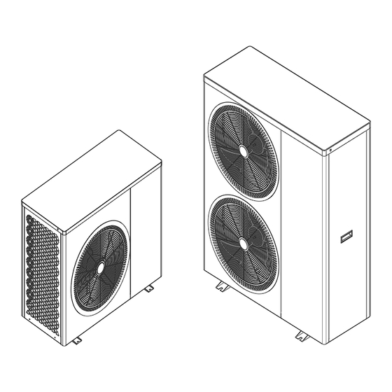
- Page 1 EVI DC Inverter Heat Pump (Built-in water pump) OPERATING INSTRUCTION MANUAL IMPORTANT SAFETY INSTRUCTIONS READ AND FOLLOW ALL INSTRUCTIONS SAVE THESE INSTRUCTIONS...
-
Page 3: Table Of Contents
Table of Contents IMPORTANT SAFETY PRECAUTIONS .................. - 2 - Section 1 Introduction ..............- 3 - Product Overview ........................- 3 - General Features ........................- 3 - Section 2 Installation ..............- 4 - Materials Needed for Installation ..................- 4 - Installation Details ........................ -
Page 5: Important Safety Precautions
IMPORTANT SAFETY PRECAUTIONS Important Notice: This guide provides installation and operation instructions for the EVI DC Inverter Air Source Heat Pump. Consult the seller with any questions regarding this equipment. Attention Installer: This guide contains important information about the installation, operation and safe use of this product. -
Page 6: General Installation Information
Heat Pump Energy Saving Tips If you do not plan to use hot water for a prolonged period, then you might choose to turn the heat pump off or decrease the temp. setting of the control several degrees to minimize energy consumption. -
Page 7: Installation
4. No potential danger of any inflammable, gas poisoning, explosion, fire, electrical shock which are associated with other heating systems. 5. A digital controller is incorporated to maintain the desired water temp.. 6. Long-life and corrosion resistant composite cabinet stands up to severe climates. 7. -
Page 8: Technical Data
Technical data Model PW030-DKZLRS-B/S PW040-DKZLRS-B PW050-DKZLRS-B Heating Condition - Ambient Temp.(DB/WB): 7/6℃,Water Temp.(In/Out):30/35℃ Heating Capacity Range (kW) 2.8~8.40 4.40~13.00 5.9~18.2 Heating Power Input Range(kW) 0.62~1.97 0.95~3.12 1.28~4.26 COP Range 4.26~4.52 4.17~4.63 4.27~4.61 DHW Condition-Ambient Temp.(DB/WB): 7/6℃,Water Temp.(In/Out):15/55℃ Heating Capacity Range (kW) 2.3~6.81... - Page 9 Model PW060-DKZLRS-B PW080-DKZLRS-B PW100-DKZLRS-B Heating Condition - Ambient Temp.(DB/WB): 7/6℃,Water Temp.(In/Out):30/35℃ Heating Capacity Range (kW) 7.5~23.0 10.2~28.0 12.8~35.0 Heating Power Input Range(kW) 1.61~5.38 2.17~6.56 2.71~8.19 COP Range 4.28~4.66 4.27~4.70 4.27~4.72 DHW Condition-Ambient Temp.(DB/WB): 7/6℃,Water Temp.(In/Out):15/55℃ 12.3~20.4 13.6~22.6 Heating Capacity Range (kW) 6.1~18.5 2.9~5.57 3.19~6.15...
- Page 10 Field assembly (if required). Appropriate site location and clearances. Proper electrical wiring. Adequate water flow. This manual provides the information needed to meet these requirements. Review all application and installation procedures completely before continuing the installation. Dimension: PW030-DKZLRS-B/S Unit:mm - 7 -...
- Page 11 PW040-DKZLRS-B PW050-DKZLRS-B PW060-DKZLRS-B - 8 -...
- Page 12 PW080-DKZLRS-B PW100-DKZLRS-B - 9 -...
-
Page 13: Exploded View
Exploded view PW030-DKZLRS-B/S PW040-DKZLRS-B - 10 -... - Page 14 PW050-DKZLRS-B PW060-DKZLRS-B - 11 -...
- Page 15 PW080-DKZLRS-B PW100-DKZLRS-B - 12 -...
-
Page 16: Installation Location
Installation Location CAUTION! 1. DO NOT install the heat pump near to hazardous materials and places 2. DO NOT install the heat pump under deep sloping roofs without gutters which will allow rain water, mixed with debris, to be forced through the unit. 3. -
Page 17: Drainage And Condensation
The plumbing pipes must be installed with proper support to prevent possible damage due to vibration.Running water pressure should be kept over 196kpa. Otherwise, booster pump should be installed. The acceptable operating voltage range should be within ±10% of the rated voltage. ... - Page 18 Schematic diagram of secondary cycle installation - 15 -...
- Page 19 Schematic diagram cycle installation - 16 -...
-
Page 20: Water Connections
Water Connections Water Connections at the Heat Pump Quick Connect fittings are recommended to be installed on the water inlet and outlet connections. It is recommended to use stainless steel or PPR pipes for the heat pump plumbing. The water inlet and outlet connection to the heat pump accepts stainless steel or PPR pipe fittings. -
Page 21: Power Supply
Power Supply If the supply voltage is too low or too high, it can cause damage and/or result in unstable operation of the heat pump unit, due to high in rush currents on start up. The minimum starting voltage should be above 90% of rated voltage. The acceptable operating voltage range should be within ±10% of the rated voltage. - Page 22 In order to correctly select the type and size of the main power cord of the device, the electricity consumption of optional accessories connected to the heat pump (auxiliary electric heater, circulation pump, solenoid valves, etc.) is also included. The table shows the maximum consumption for the combination of heat pump and auxiliary electric heater.
- Page 23 which provides a control signal to the contactor that switches on and off the electric heater properly selected for the heating system. Parameters of the signal controlling the operation of the additional electric heater: ~230V/50Hz max 2A. Note: Do not connect additional heaters directly to the heat pump's control terminals! Connecting devices to work in a cascade system When using the cascade function, it is necessary to set the correct number of units in cascade mode on the heat pump's main board via Switch 1-4.
-
Page 24: Electrical Wiring Diagram
Electrical Wiring Diagram 1. Single phase system (PW030/040-DKZLRS-B/S) 2. Three phase system (PW040/8050/060-DKZLRS-B) - 21 -... - Page 25 3. Three phase system (PW080/100-DKZLRS-B) - 22 -...
-
Page 26: Operating Heat Pump
Section 3 Operating Heat Pump Controller Panel 1. Display Icon Mode Meaning Heating mode Hot water mode Cooling mode Heating and Hot water Mode (Hot water function as priority) Cooling and Hot water Mode (Hot water function as priority) Smart mode Power mode Slient mode Vacation mode... -
Page 27: Definition Of Buttons
Defrosting Antifreezing 2. Definition of Buttons Button Description Function On/off turn on or turn off the heat pump. Mode switch the operating mode of the heat pump. Timer set timer switch and working weekdays. query running parameters, check and set system parameters, Setting error code records, Wifi connection, etc. -
Page 28: Wire Controller Operation
Check the inlet water and outlet water operation curves and curve operation power curves. System Check the version information of the system motherboard and parameters the remote control program. Language Language selection 3. Wire Controller Operation 3.1. START / STOP THE HEAT PUMP In the main interface, press the "ON/OFF"... -
Page 29: Clock Setting
3.3. RUNNING MODE SETTING/OPERATING MODE SELECTION In the main interface, press the "MODE" key for 1 second to enter the operation mode, frequency mode and holiday mode selection interface, and select the required operation mode (parameter setting model) and frequency mode of the unit;... -
Page 30: Timer Setting
3.5. TIMER SETTING: ◎In the main interface, press TIMER button to enter timing setting interface. ◎In the WEEK column, users can select which weekdays to perform timer switch. When the weekday button (From MON. to SUN.) turns highlight white, the timer will perform on that day. -
Page 31: Forced Defrosting
3.6. OPERATION PARAMETER QUERY Press the "SETTING" key in the main interface to enter the setting interface. Then press "UNIT STATUS" to enter the unit list interface, select the corresponding unit to enter the "Parameter Query", and check the operation status of the heat pump. The status table is as follows: Forced defrosting In the unit selection interface of the query status, press and hold the corresponding unit number to pop up the forced defrosting selection interface of the corresponding unit. - Page 32 ◎List of operation parameters Code Description Remark Water inlet temp. -30~99℃ Water outlet temp. -30~99℃ Ambient temp. -30~99℃ Exhaust gas temp. 0~125℃ Return gas temp. -30~99℃ Evaporator coil temp. -30~99℃ Inlet temp. of economizer -30~99℃ Outlet temp. of economizer -30~99℃ Cooling coil temp.
- Page 33 3.7. Check the energy consumption curve Press the "SETTING" key in the main interface to enter the setting interface. Then click “Run the curve” to enter the energy consumption curve interface, click at the bottom of the interface to switch "temperature curve", "operating power curve" and "COP curve". ", "heating capacity", "daily power consumption curve", "monthly power consumption curve", "annual power consumption curve".
- Page 34 USER PARAMETERS QUERY & SETTING ◎ Press “SETTING” in the main interface to enter setting interface, then press “USER PARAMETERS” to enter parameter query and setting. Below lists shows the code, definition, range and default value. ◎ List of user parameters Code Definition Settable Range...
- Page 35 Defrost exit temperature 1℃~40℃ 15℃ Defrosting environment and evaporator 0℃~15℃ 5℃ coil temp. difference 1 Defrosting environment and evaporator 0℃~15℃ 5℃ coil temp. difference 2 Ambient temp. for defrosting 0℃~20℃ 17℃ 0~30 days High temperature disinfection cycle Disinfection function is not days executed when set to 0 High temperature disinfection start time...
-
Page 36: Restore Factory Settings
Number of on-line units 1~255 Control address Smart grid enable No、Yes SG operating time 0-600 min 180min 0:disable 1:backup E-heater 2: water tank booster heater Electric heating mode 3: backup e-heater + Tank booster heater 0:Water inlet temperature Water temperature control mode 1:Water outlet temperature 3.8 Restore factory settings In the upper right corner of the factory parameter R interface, there is a parameter reset... - Page 37 High Temperature Antisepsis Function: (when hot water function is selected) ◎ High temperature Antisepsis cycle is once every 7 (P17) days; ◎ When entering the high temperature Antisepsis, the water tank electric heater will be forced to turn on. ◎ During the Antisepsis process, if the water tank temperature > 60℃(the maximum settable temperature), then the compressor will not start, but only start electric heating;...
- Page 38 Auxiliary Electric Heater for Water Tank ◎ Start conditions (all below conditions must be met at the same time) 1) In hot water mode; 2) The compressor runs for P27(30)minutes; 3) There is a demand for hot water, and the temperature of the water tank is ≤55℃; 4) The pump is running 5) Water tank Electric heater was enabled (P30 was set as 2 or 3)
- Page 39 6) Circulation pump shut-down E-heater be shut-down when any of above conditions met SMART GRID ◎When the smart grid function parameter is selected to be enabled (S01 = 1), the heat pump starts running the smart grid function SMART GRID Operating State Increased operation Normal operation...
-
Page 40: Initial Start-Up Precautions
General Operating Guide Initial Start-up Precautions rst boot-strap and Running state checks 1. To ensure the power same as the product nameplate required power. 2. Unit electrical connections: Check if power supply wire track and connection is ok; if ground wire is properly connected;... - Page 41 water lack alarm. 2.4 Regular clean water system according to maintenance request. 2.5 Pay attention to antifreeze when the environment temp. is less than zero in winter. 2.6 Safety Precautions User can’t self-install the unit, ensure agent or specialized install company to do, or else maybe cause safety accident and affect the use effect.
-
Page 42: General Maintenance
Section 4 General maintenance Controller Error Codes ◎ If there’s error in the heat pumps, the error code and error definition will be displayed in the main interface, and saved the record in FAULTY column inside the SETTING interface. The following Common Error Codes will be displayed on the controller panel: ◎... - Page 43 3. Water side heat exchanger has 2. Replace the filter scale 3. Scale removal 4. The inlet temperature probe 4. Reconnect the water inlet falls off (the actual water temperature probe temperature is too high) System: 1. The evaporator fin is dirty and 1.
- Page 44 1. The water outlet temperature is 1. Check whether the water valve higher than the system protection or water pump is started Cooling outlet water value, the water flow is small, and 2. Clean the pipes and exhaust Er 23 temp.
- Page 45 ◎ Detailed error code list for Er 20: Error Definition of Description Solution suggestion Code Error or Protection IPM Over-current 1. The IPM overloaded or 1 Ensure that the ring temperature, overheated water temperature, water flow, etc. 2. The U,V,W driver are within the operating range of short-circuited the unit;...
-
Page 46: Owner Inspection
AC Input low 1. The input voltage too low 1. Ensure that the input voltage is voltage 2. The current transformer normal damaged during transportation 2. Ensure that the current transformer works properly IPM too high 1. The fan is faulty or the air 1. -
Page 47: Troubleshooting
Troubleshooting Use the following troubleshooting information to resolve issues/problems with your DC Inverter heat pump. WARNING — RISK OF ELECTRICAL SHOCK OR ELECTROCUTION. Ensure that all high voltage circuits are disconnected before commencing heat pump installation. Contact with these circuits could result in death or serious injury to users, installers or others, due to electrical shock and may also cause damage to property. -
Page 48: Maintenance
Maintenance The DC Inverter air source heat pump unit is highly automation device. If the units are cared and maintained effectively regularly , the operation reliability and the lifetime of the unit will be highly improved. Important tips below shall be paid more attention to when doing the maintenance: 1. -
Page 49: Common Faults And Debugging
Common Faults and Debugging ◎The user must hire the professional maintenance staff to fix if the unit has any problems during working. The maintenance staff might refer to the chart to debug. Error Status Possible reason Solution Power fault Put off the power switch, check the Wiring loose power supply Heat pump not... -
Page 50: Wifi Connection And Operation
Section 5 WIFI Connection and Operation APP Download ◎Please go to “Google Play Store” or “Apple App Store” and search “Smart Life” or “Tuya Smart” then download. See below figures. WIFI Connect Method : bluetooth mode: The 1 step: ◎By default, it can be connected within 10s after the first power-on, and it needs to be connected by pressing buttons after 10 seconds. - Page 51 ◎Exit the network configuration status after 3 minutes, the " " icon stops flashing, and the WIFI module is no longer networked. If you want to configure the network again, you need to click the "Add Device" button on the WIFI interface again. The 2 step: ◎Turn on the phone's bluetooth...
- Page 52 The 4 step: ◎ When the connection is successful and the system prompts "Added successfully", then the network configuration is successful. Click "Done" to entry Homepage - 49 -...
-
Page 53: Software Function Operation
Software function operation Interface Introduction ◎After the device is successfully bound, enter the "My house Heat Pump " (device name can be modified) operation page. ◎Click "My house Heat Pump" in "All Devices" in the main interface of "Smart Life" APP to enter the "My house Heat Pump"... -
Page 54: Mode Setting
Mode setting ◎Click "Work mode" on the main interface of the equipment operation to switch mode, and the mode selection interface will pop up as shown in the figure below, just click the mode you need to select. Water Temp. Setting ◎In the Setting interface, click“Water Temp. -
Page 55: User Setting
User setting High Temperature Antisepsis Function: (when hot water function is selected) ◎ High temperature Antisepsis cycle is once every 7 days(Cancel this function when the selection is 0); ◎ When entering the high temperature Antisepsis, the water tank electric heater will be forced to turn on. - Page 56 Pset (heating target temperature) =20℃ + (Target temperature compensation coefficient ÷10) * (Heating compensation temperature point - current ambient temperature) ◎ The above different curves stands for the different value of Target temperature compensation coefficient. (When Target temperature compensation coefficient=1, the actual value is 0.1) ◎...
- Page 57 - 54 -...
- Page 58 ◎In the timer setting, slide the hour/minute up and down to set the timer time,and set the repeating week and on/off, press the upper right corner to save, as shown in the below Fig. Minutes Available select repeating times Available setting timer power on/off Power Consumption Curve View ◎In the Setting interface, click ”Power Statistics Module”...
- Page 59 Equipment sharing ◎Share the bound device, the sharer operates in the following sequence. ◎After successful sharing, the list will be increased and show the shared person. ◎To delete the shared person, long press the selected user, the delete interface will pop up, click "Delete".
Need help?
Do you have a question about the PW030-DKZLRS-B and is the answer not in the manual?
Questions and answers