Table of Contents
Advertisement
Quick Links
Advertisement
Table of Contents

Summary of Contents for ZF SCALAR EVO Flow
- Page 1 551 030 0xx 0 Installation Guide SCALAR EVO Flow...
-
Page 2: Table Of Contents
Euroscan TMS / Euroscan X1/X2 ....................20 Thermo King i-Box ........................21 REB i-Box ..........................23 Thermo King BlueBox ....................... 25 Thermo King TranScan / (TK)DL-PRO ..................28 SCALAR EVO Flow Installation Guide Confidential Information V0.11 Page 2 of 61... - Page 3 Step 4 – 551 030 0xx 0 Position ...................... 58 Installing the Interface Behind the Vehicle Dashboard ..............58 Installation Example ......................... 59 Finalizing the Hardware Installation ....................60 Contact Information ......................... 61 SCALAR EVO Flow Installation Guide Confidential Information V0.11 Page 3 of 61...
-
Page 4: Before The Installation
The installation of the on-board computers can be carried out either by technical engineers of ZF, or by a skilled person. A lot of ZF customers prefer to do the installation themselves: the building-in of the on-board computer can then be combined with regular vehicle maintenance services, which allows for a more efficient use of time. -
Page 5: Product Article Code
1-9 = Functional version Approvals CE Approval 551 030 0xx 0 EU Declaration of Conformity EEC Type Approval E/ECE/324 Addendum 9: Regulation No. 10-06 – E6-10R06 XXXX Disposal SCALAR EVO Flow Installation Guide Confidential Information V0.11 Page 5 of 61... -
Page 6: Best Practices In Installation
ZF wishes to point out that activities which require welding to the vehicle can cause damage to the electronics of the on-board computer. It is imperative that the device is disconnected when carrying out such activities. -
Page 7: Installation Flow
Connecting the SOS Kit Step 3 – Check the Installation Page 49 Step 4 – 551 030 0xx 0 Position Page 58 • Installing the Interface Behind the Vehicle Dashboard SCALAR EVO Flow Installation Guide Confidential Information V0.11 Page 7 of 61... -
Page 8: Step 1 - Components
(Article code: 551 031 021 0) FMS connector kit (Article code: 551 013 011 4) RDD connector kit (Article code: 551 013 021 4) Tachograph connector kit (Article code: 551 013 031 4) SCALAR EVO Flow Installation Guide Confidential Information V0.11 Page 8 of 61... -
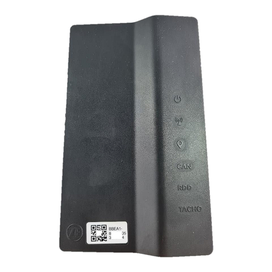
Page 9: Description 551 030 0Xx 0
GPRS Status RDD Connection Status information.) Tachograph Connection TACHO GPS Status Status QR code + device serial number: BBE(x)1-XXXXXXXXXXXXXXX (15 digits) Label (top) Label (bottom) Notches for Cable Ties SCALAR EVO Flow Installation Guide Confidential Information V0.11 Page 9 of 61... -
Page 10: Step 2 - Connecting The Hardware
Step 2 – Connecting the Hardware IMPORTANT During the whole connection procedure, the voltage must be turned OFF. Only technical engineers who have received installation training by ZF are allowed to handle the on-board computer connections. Hardware Connections All hardware connections can be found on the side of the unit. - Page 11 Tachograph. 2. When the driver stops driving and turns the ignition key to the “Radio ON” position, the question “Please choose an activity” will not be displayed on the on-board computer. SCALAR EVO Flow Installation Guide Confidential Information V0.11...
-
Page 12: Connecting To The Standard Fms Connector
Consult the Truck-specific Installation Guides (TIG) for more information on truck-specific signals. During the entire connection procedure, the voltage must be turned off! FMS Connector SCALAR EVO Flow Installation Guide Confidential Information V0.11 Page 12 of 61... -
Page 13: Connecting The Digital Tachograph (D8)
If the seal of the Tachograph has been broken during assembly, or if signals from the Tachograph are being diverted to the on-board computer, the Tachograph must be resealed by an authorized organization. ZF and its distributors do NOT accept any responsibility for possible infringements against local legislation. -
Page 14: Connecting The Can Bus
Signal Black CAN-L CAN Bus Connector White CAN-H LEASE Regardless of what changes you are about to make to the CAN Bus connection, always switch off tension first! SCALAR EVO Flow Installation Guide Confidential Information V0.11 Page 14 of 61... -
Page 15: Connection To Can Bus Via The Fms Interface
The FMS Gateway is delivered, installed, and activated by the truck manufacturer. Wiring between the FMS Gateway and the Interface: The CAN BUS Connector Wire Color Signal Black CAN LOW White CAN High SCALAR EVO Flow Installation Guide Confidential Information V0.11 Page 15 of 61... -
Page 16: Connection To Can Bus Using Tx-To-Can
Connect the CAN wires to the correct location in the truck using the CANcliQ. The CAN Bus wire colors depend on the vehicle type. As a result, we refer to the vehicle passports (provided by your ZF Project Engineer) to find the location of the CAN Bus wires in the truck. -
Page 17: Connecting The Remote Data Download
Connect the grey and white wires from the Power I/O cable (article code: 551 031 011 0) to the C-Connector (red) at the back of the digital Tachograph. A red Tachograph connector (C-Connector) will be provided by ZF (RDD connector kit (article code: 551 013 021 4)). Wire Color... -
Page 18: Rdd Via Fms
Stoneridge The Tachograph firmware version must be at least SE 5000 7.1. The version can be found on a Tachograph printout. For more information, consult https://help.tx-connect.com/prodB/tx-connect/Content/UIO/English/TX- CONNECT.htm#Troubleshooting/RDD_Tacho_compatibility.htm SCALAR EVO Flow Installation Guide Confidential Information V0.11 Page 18 of 61... -
Page 19: Connecting The Temperature Recorder
Carrier DataCOLD 500 Third party Carrier DataCOLD 600 / Euroscan X3 Partner protocol Carrier Direct MPORTANT Grey wire must be isolated when not connected. SCALAR EVO Flow Installation Guide Confidential Information V0.11 Page 19 of 61... -
Page 20: Euroscan Tms / Euroscan X1/X2
Euroscan TMS / Euroscan X1/X2 Connect the pins on the ZF device to the correct pins on the connector blocks of the temperature recorder. In case COM1 is already occupied, you need to connect to COM2. Setting the Reefer Protocol After connecting the hardware, the recorder protocol must be set to the correct protocol. -
Page 21: Thermo King I-Box
This installation requires the following firmware version: • Firmware i-Box: REV 5309 or higher Connect the pins on the ZF device to the correct pins on the connector blocks of the temperature recorder. SCALAR EVO Flow Installation Guide Confidential Information V0.11... - Page 22 3. Start the Wintrac software on the PC. 4. Select Configure i-Box in the Tools menu. 5. Make sure that Third-party protocol is selected under “Protocol Selection”. SCALAR EVO Flow Installation Guide Confidential Information V0.11 Page 22 of 61...
-
Page 23: Reb I-Box
REB I i-Box REV A031 with firmware version 5506 and for REB II i-Box with firmware version 5370. 1. Find the 3 -party REB wiring harness. SCALAR EVO Flow Installation Guide Confidential Information V0.11 Page 23 of 61... - Page 24 However, in case another system was connected to the REB i-Box before, it is possible that the protocol needs to be reconfigured (cf. Setting the Reefer Protocol on page 22). SCALAR EVO Flow Installation Guide Confidential Information V0.11 Page 24 of 61...
-
Page 25: Thermo King Bluebox
1. Plug in the i-BOX harness 35 BlueBox connector. 2. Plug in the 8-pin CAN connector to the 8-pin CAN1 on the controller. Make sure that the connector clip is secured. SCALAR EVO Flow Installation Guide Confidential Information V0.11 Page 25 of 61... - Page 26 (J12) pin of SR3 and tighten the nut using a spacer. Insert this CH wire into TERMINAL-RING BLUE (crimp, solder, and insulate) and connect to CH terminal (J23) of SR3. SCALAR EVO Flow Installation Guide Confidential Information V0.11 Page 26 of 61...
-
Page 27: Checking The Installation
On 551 030 0xx 0, the temperature control system is connected to COM 1 or COM 2 on the on-board computer. Connect the pins on the ZF device to the correct pins on the temperature recorder. SCALAR EVO Flow Installation Guide Confidential Information V0.11... -
Page 28: Thermo King Transcan / (Tk)Dl-Pro
RS232 port 551 010 0xx 0 (5/6) CON 2 Wire color Signal Pin No. Signal Yellow Black Brown Setting the Reefer Protocol The TranScan / TKDL-PRO temperature recorder does not require specific configuration. SCALAR EVO Flow Installation Guide Confidential Information V0.11 Page 28 of 61... -
Page 29: Thermo King Touchlog
515.023. Press to consult the current firmware version in the Quick Info menu. Please contact your local Thermo King dealer in case the firmware needs to be updated. SCALAR EVO Flow Installation Guide Confidential Information V0.11 Page 29 of 61... - Page 30 TouchLog module from going into sleep mode. However, the TouchLog module will consume more power, as it no longer goes into standby mode when it is not used. SCALAR EVO Flow Installation Guide Confidential Information V0.11 Page 30 of 61...
- Page 31 1. 4. The settings for serial port 1 should look like as shown in the illustration, in order to read data from the port. SCALAR EVO Flow Installation Guide Confidential Information V0.11 Page 31 of 61...
-
Page 32: Carrier Datacold 500
2. Connect the wires of the open-end reefer cable to the correct pins on the temperature recorder. In case COM1 is already occupied, you need to connect to COM2. SCALAR EVO Flow Installation Guide Confidential Information V0.11 Page 32 of 61... - Page 33 6. Press the yellow button until Third-party protocol is displayed. 7. Press the green button once to confirm your changes. 8. Press the button twice to return to the main menu SCALAR EVO Flow Installation Guide Confidential Information V0.11 Page 33 of 61...
-
Page 34: Carrier Datacold 600 / Euroscan X3
• The protocol of the COM port (mostly COM2) for the communication between the reefer unit and the DataCOLD 600 recorder must be set to Carrier Advance (not “Vector”). SCALAR EVO Flow Installation Guide Confidential Information V0.11 Page 34 of 61... - Page 35 6. Press the yellow button until Partner protocol is displayed. 7. Press the green button once to confirm your changes. 8. Press the button twice to return to the main menu. SCALAR EVO Flow Installation Guide Confidential Information V0.11 Page 35 of 61...
-
Page 36: Carrier Direct
However, Carrier does not allow removing the SATCOM connector. Always order the specific connector (for serial connections) to plug in on this SATCOM SATCOM connector connector. Connection scheme Connection Scheme SCALAR EVO Flow Installation Guide Confidential Information V0.11 Page 36 of 61... -
Page 37: Additional Requirements
For Supra models, a chip needs to be switched on the reefer controller board. This chip can be ordered at Carrier. Once the chip or license is loaded, one- and two-way communication is enabled on the reefer unit. Supra chip SCALAR EVO Flow Installation Guide Confidential Information V0.11 Page 37 of 61... -
Page 38: Trs
1. Open the temperature recorder to access the connector blocks. 2. Connect the wires of the open-end reefer cable to the correct pins at the back of the temperature recorder. SCALAR EVO Flow Installation Guide Confidential Information V0.11 Page 38 of 61... -
Page 39: Connecting The External Smart Card Reader
2. The Smart Card Reader must not be exposed to direct sunlight. 2. After cleaning the surface, remove the backing paper (from the backside of the Smart Card Reader) and firmly press the Smart Card Reader onto the surface. SCALAR EVO Flow Installation Guide Confidential Information V0.11... - Page 40 To achieve a good bond, use the entire adhesive surface of the Smart Card Reader. 3. Place the Smart Card Reader with the card reader slot directed toward the front of the vehicle. 4. Wait 72 hours after fixing the Smart Card Reader before use. SCALAR EVO Flow Installation Guide Confidential Information V0.11...
-
Page 41: Using The Smart Card Reader
To remove the Smart Card: Slightly lift the Smart Card and then slide out of the Smart Card Reader. Lift the Smart Card and then slide out of Smart Card Reader SCALAR EVO Flow Installation Guide Confidential Information V0.11 Page 41 of 61... -
Page 42: Tx-Connect Configuration
3. In the Tach ID field, enter 000 and then the ID Card alphanumeric number. For Example: • ID Card Number: TRA10012345 • In Tacho ID field: 000TRA10012345 4. Click Save (lower right-hand corner). SCALAR EVO Flow Installation Guide Confidential Information V0.11 Page 42 of 61... -
Page 43: Connecting Pto
K30 VBAT Blue K15 IGNITION Yellow TACHO White RDD HIGH The digital input is ACTIVE LOW. IMPORTANT ON state (> 3.4 V) and OFF state (< 3.0 V) SCALAR EVO Flow Installation Guide Confidential Information V0.11 Page 43 of 61... -
Page 44: Connecting The Pto Extension Kit
Remark: PTO kit contact 5/87A and 8/87 are not used. The digital inputs PTO2, PTO3, and PTO4 are ACTIVE HIGH. IMPORTANT ON state (> 6.4 V) and OFF state (< 5.0 V). SCALAR EVO Flow Installation Guide Confidential Information V0.11 Page 44 of 61... -
Page 45: Connection To On-Board Computer
The RDD cable is then connected in parallel with the PTO extension kit and the digital Tachograph. To make the parallel connection the RDD cable can be cut. SCALAR EVO Flow Installation Guide Confidential Information V0.11 Page 45 of 61... -
Page 46: Rdd Via Fms
To make the parallel connection the RDD cable can be cut. PTO Connection Wire Color Power I/O FMS Gateway PTO Kit Cable CAN-HIGH 7 / H White wire CAN-LOW 9 / L Grey wire SCALAR EVO Flow Installation Guide Confidential Information V0.11 Page 46 of 61... -
Page 47: Connecting The Sos Kit
Connect the SOS button to INPUT 1 = PTO1 or INPUT 2 = PTO 6 on Connector 4 (see picture above) on the on-board computer. The SOS button must be powered with a 24V fused power supply. SCALAR EVO Flow Installation Guide Confidential Information V0.11... -
Page 48: Connection To Pto Extension Kit
SOS Button – Behavior Button State Contact State Result Button not pressed OPEN Orange LED OFF - PTO state OFF Button pressed CLOSED Orange LED ON - PTO state ON SCALAR EVO Flow Installation Guide Confidential Information V0.11 Page 48 of 61... -
Page 49: Step 3 - Check The Installation
CAN connection OK CAN connection status CAN connection NOK. GREEN RDD connection OK. RDD connection status RDD connection NOK. GREEN Tachograph connection OK. Tachograph connection Tacho status Tachograph connection NOK. SCALAR EVO Flow Installation Guide Confidential Information V0.11 Page 49 of 61... -
Page 50: Verifying The Installation With Tx-Config
TX-CONFIG requires an active Internet connection and is supported on Android 2.3 and all later versions. Contact the Transics Service Desk in case a problem occurs during the installation. SCALAR EVO Flow Installation Guide Confidential Information V0.11 Page 50 of 61... -
Page 51: Registering And Configuring 551 030 0Xx 0
The smartphone’s barcode scanner automatically launches. 4. Scan the QR code from the label on the 551 030 0xx 0 on-board computer device (located on the front or the backside of the unit). SCALAR EVO Flow Installation Guide Confidential Information V0.11 Page 51 of 61... - Page 52 If the serial number is already linked to a vehicle in the back office, the license plate of the vehicle will be filled in already. Modify it, if necessary. 7. Press to confirm. SCALAR EVO Flow Installation Guide Confidential Information V0.11 Page 52 of 61...
- Page 53 551 030 0xx 0 calculates kilometers based on the vehicle position. 551 030 0xx 0 automatically AutoDetect chooses its source based on the available sources. 10. Press to continue. SCALAR EVO Flow Installation Guide Confidential Information V0.11 Page 53 of 61...
- Page 54 15. The mileage of 551 030 0xx 0 must be set to the value on the Tachograph. 16. Press to continue. LEASE Km is only displayed if either “Vehicle”, “GPS” or “AutoDetect” was selected in the Km source screen (see above). SCALAR EVO Flow Installation Guide Confidential Information V0.11 Page 54 of 61...
- Page 55 You can find the Tachograph version number: • On the label behind the Tachograph paper roll • Via the Tachograph serial number (cf. RDD Tachograph Compatibility on page 18). SCALAR EVO Flow Installation Guide Confidential Information V0.11 Page 55 of 61...
-
Page 56: Device Health
Device Health indicates the status for the following sections: • Communication • Entries • Tacho • CAN Bus • Press an item to display its details. Press Back to return to the Device Health overview. SCALAR EVO Flow Installation Guide Confidential Information V0.11 Page 56 of 61... - Page 57 • Satellites: Number of satellites covering the vehicle. For a good GPS position a minimum of 3 satellites with preferably 5 satellites are required. • Map: Current position SCALAR EVO Flow Installation Guide Confidential Information V0.11 Page 57 of 61...
-
Page 58: Step 4 - 551 030 0Xx 0 Position
Do not use the device at an altitude above 2000 meters. • Avoid the presence of any material within 25 mm around the GNSS antenna, this can disturb the antenna’s performance. SCALAR EVO Flow Installation Guide Confidential Information V0.11 Page 58 of 61... -
Page 59: Installation Example
Minimum of 25 mm of free space around the unit Good Installation Example No cabling around the unit Installed on a PLASTIC surface Bad Installation Example Too much cabling around the unit! Installed on a METAL surface! SCALAR EVO Flow Installation Guide Confidential Information V0.11 Page 59 of 61... -
Page 60: Finalizing The Hardware Installation
Secure all Connected Wires After connecting the power cable and all other hardware (CAN Bus, digital Tachograph, and so on) to the interface, ZF recommends using cable ties to relieve tension from the connectors. Secure the power cable and all other connectors (FMS, RDD, and K-Line) using a cable tie. -
Page 61: Contact Information
Please check with your ZF project engineer for a release of this guide in your language. All rights reserved. The material, information and instructions for use contained herein are the property of ZF. The material, information and instructions are provided on an AS IS basis without a warranty of any kind. There are no warranties granted or extended by this document.
Need help?
Do you have a question about the SCALAR EVO Flow and is the answer not in the manual?
Questions and answers