Table of Contents
Advertisement
Quick Links
Advertisement
Table of Contents

Related Manuals for Videotec COMB

Summary of Contents for Videotec COMB
- Page 1 ENGLISH COMB Communication box in polycarbonate English - Instruction manual...
-
Page 3: Table Of Contents
Contents E N G L I S H 1 About this manual ........................5 1.1 Typographical conventions ..............................5 2 Notes on copyright and information on trademarks ............5 3 Safety rules ..........................5 4 Identification ..........................8 4.1 Product description and type designation........................8 4.2 Product overview ................................... - Page 4 12.3 Network ....................................19 12.4 Analogue video .................................. 19 12.5 I/O interface ..................................19 12.6 Environment ..................................19 12.7 Certifications ..................................19 12.8 Certifications - Railway applications ........................... 19 12.9 Certifications - Marine applications ..........................20 13 Technical drawings .......................20 MNVCCOMB_2222_EN...
-
Page 5: About This Manual
1 About this manual 3 Safety rules Read all the documentation supplied carefully DANGER! before installing and using this product. Keep the High level hazard. manual in a convenient place for future reference. Risk of electric shock. Disconnect the power supply before proceeding with any 1.1 Typographical conventions operation, unless indicated otherwise. - Page 6 • Make sure the product is to be secured to building • Whenever replacing the parts as indicated, before operation. always use VIDEOTEC original spare parts and meticulously follow the maintenance instructions • Any change that is not expressly approved by the supplied with every spare parts kit.
- Page 7 • Installation category (also called Overvoltage INFO Category) specifies the level of mains voltage Description of system specifications. surges that the equipment will be subjected We recommend reading this part carefully to. The category depends upon the location in order to understand the subsequent of the equipment, and on any surge voltage stages.
-
Page 8: Identification
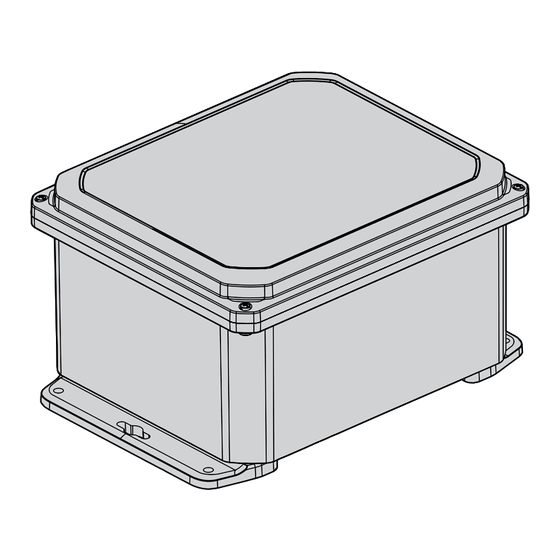
4 Identification • One or two VIDEOTEC fixed cameras with or without the relevant VIDEOTEC washers. 4.1 Product description and type 1 or 2 VIDEOTEC designation fixed cameras Main COMB is a communication box equipped with power supply everything necessary to connect one or more IP or analogue cameras and the relevant washer. -
Page 9: Product Overview
Improper use of the appliance can cause serious hazards, risking the safety of personnel and of the installation. 4.5 Model identification COMB - CONFIGURATION OPTIONS Input voltage Revision COMB 1 from 220Vac up to... -
Page 10: Preparing The Product For Use
5 Preparing the product for 5.4 Product opening During product opening and closing operations, be careful not to damage the 5.1 Unpacking cover gasket. When the product is delivered, make sure that the Unscrew the 4 screws and remove the cover. package is intact and that there are no signs that it has been dropped or scratched. -
Page 11: Cable Entry
5.5 Cable entry To maintain the IP degree of protection of the product, use cable glands with adequate IP. To maintain UL certification, the cable glands used must be UL certified. All the cable glands must be suitable for the use conditions and installed correctly. The product is supplied without drilling. -
Page 12: Fixing Flanges Assembly
If you want to connect a product from the NXPTZ or NXPTZ SERIES2 range to COMB, you must make a 32mm diameter hole in the box. Once the desired hole is made, assemble the cable... -
Page 13: Installation
6.1.1 Connector board description 24Vac output, for from 0.2mm² (24AWG) washer and command up to 2.5mm² (13AWG) relay input from the J26-J27 VIDEOTEC camera 24Vac output, for from 0.2mm² (24AWG) washer and command up to 2.5mm² (13AWG) relay input from the VIDEOTEC camera BNC (Video 1) IN –... -
Page 14: Connection Of The Main Power Supply Line
6.1.2 Connection of the main power 6.1.3 Products connection to the 24Vac supply line power supply line Connect the 24Vac power supply cables of the CAUTION! TNV-1 installation type. The devices (PTZ or fixed camera) to the connectors J6 installation is type TNV-1, do not connect it and J7. -
Page 15: Connectors For The Washer (Wasnx)
Consult the installation manual of the washer for the relevant specifications. Connect the command the relevant specifications. Connect the command contacts relay of the VIDEOTEC PTZ or fixed cameras contacts relay of the VIDEOTEC PTZ or fixed cameras and the power supply cables (24Vac) of the washer and the power supply cables (24Vac) of the washer according to the diagram below (Fig. -
Page 16: Description Of The Switch Board
Consult the installation manuals of the devices to connect for specifications on the Ethernet cable. 6.1.10 Using the splice tray COMB is equipped with a splice tray to host the fiber optics. Remove the screws (01) and take out the splice tray (02) (Fig. -
Page 17: Switching On
Arrange the fibre optics as indicated in the figure, Position the splice tray in place and fasten it using use the nylon ties supplied to fasten them (Fig. 17, the previously removed screws (Fig. 18, page 17). page 17). Fig. 17 Fig. -
Page 18: Maintenance
Cleaning should be done with mild soap diluted with water. When contacting VIDEOTEC for assistance please provide the serial number and the identification code of the model. PROBLEM The product does not go on. -
Page 19: Technical Data
UL 62368-1) Vibration test: EN50130-5, EN60068-2-6 Possible system configurations: UL certification (UL60950-1, CAN/CSA C22.2 No. • A VIDEOTEC PTZ camera with or without the 60950-1-07, UL62368-1, CAN/CSA C22.2 No. 62368-1- relevant VIDEOTEC washer. 14): cULus Listed • One or two VIDEOTEC fixed cameras with or Electromagnetic compatibility (North America): FCC without the relevant VIDEOTEC washers. -
Page 20: Technical Drawings
The indicated measurements are expressed in millimetres. Ø 8.4 336.6 336.3 285.5 368.3 Fig. 19 COMB. Headquarters Italy VIDEOTEC S.r.l. Via Friuli, 6 - I-36015 Schio (VI) - Italy Tel. +39 0445 697411 - Fax +39 0445 697414 Email: info@videotec.com www.videotec.com...
Need help?
Do you have a question about the COMB and is the answer not in the manual?
Questions and answers