
Related Manuals for Sartorius Sterisart Universal Gen 4


Summary of Contents for Sartorius Sterisart Universal Gen 4
- Page 1 Operating Instructions Original Operating Instructions Sterisart Universal | Gen 4 ® 16421-B | 16421-E | 16421-A Peristaltic Pump 1000127034...
-
Page 3: Table Of Contents
Contents Contents 1 About These Instructions . . . . . . . . . . . . . . . . . . . . . . . . . . 6 Operating Elements in Task Display . - Page 4 Contents 6 Commissioning . . . . . . . . . . . . . . . . . . . . . . . . . . . . . . . . . . . 48 Performing a Configured Workflow Connecting the Control Unit to the Device (Only for Advanced Version) .
- Page 5 17 Sartorius Service . . . . . . . . . . . . . . . . . . .
-
Page 6: About These Instructions
About These Instructions About These Instructions Validity These instructions are part of the device; they must be read in full and stored. These instructions apply to the device in the following versions: Device Item Number Sterisart Universal | Gen 4 - Basic, without control unit 16421-B ®... -
Page 7: Symbols Used
About These Instructions Symbols Used 1.4.1 Warnings in Operation Descriptions WARNING Denotes a hazard that may result in death or serious injury if it is not avoid- CAUTION Denotes a hazard that may result in moderate or minor injury if it is not avoided. -
Page 8: Safety Instructions
Only the maintenance tasks described in these instructions should be car- ried out. For maintenance tasks that need to be carried out by Sartorius Ser- vice, contact Sartorius Service. Sartorius recommends that any repair work, even that carried out after the end of the warranty period, is carried out by Sartorius Service or after con- sulting with Sartorius Service. -
Page 9: Qualifications Of Personnel
Only use the original power supply cable. If the power supply cable needs to be replaced: Contact Sartorius Ser- vice. Do not repair or modify the power supply cable. Operating Instructions Sterisart Universal | Gen 4 ®... -
Page 10: Danger Of Fire Due To Corrosive And Explosive Liquids
— Risk of injury to persons — Damage, malfunctions, or failure of the device Only use accessories, consumables, and spare parts that are approved by Sartorius for this device. Personal Protective Equipment Personal protective equipment protects against hazards arising from the device. -
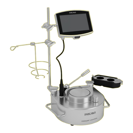
Page 11: Device Description
Device Description Device Description Device Overview Fig. 1: Sterisart Universal | Gen 4 bench-top version (with and without control unit, example) ® Pos . Name Description Control unit Protective cap Protects the control unit connection from water and dust. Clamping bracket- Clamps the tubes into the sterility test units. -
Page 12: Lever
Device Description Lever The lever is intended to position the clamping bracket. The lever must be moved manually by the operator. Fig. 2: Lever position (tubing not shown, example) Pos . Name Description Lever closed The clamping bracket remains on the pump head. This fixes the tubes to the pump head. -
Page 13: Stand And Bottle Holder
Device Description Stand and Bottle Holder Fig. 3: Stand and bottle holder, mounted on the pump unit Pos . Name Description Stand Intended to attach components, e.g. control unit and bottle holder. Bottle holder clamp — Comprises an inner part with fastening screw. —... -
Page 14: Control Unit
Device Description Control Unit The control unit is intended to control the pumping process, e.g. to manually configure and perform pumping pro- cesses and generate reports. Fig. 4: Control unit, mounted on the stand Pos . Name Description Connection arm Is intended to attach to the stand. -
Page 15: Collection Vessel
Device Description Collection Vessel Fig. 5: Run-off vessel, mounted on the pump unit Pos . Name Description Fastening screw Intended to attach components to the pump unit. Collection vessel lug — Includes a pin for inserting the collection vessel. — Connects the collection vessel with the pump unit. Cover for collection vessel Is intended to insert the sterility test units. -
Page 16: Pressure Sensor
Device Description Pressure sensor There are 2 pressure sensors installed in the device. The pressure sensor is intended to measure the pressure in the sterility test units. Devices with a control unit include pressure monitoring and pressure control. The pressure thresh- old and overpressure response can be configured (see Chapter “3.7 Pressure Monitoring and Pressure Control (Only Devices With Control Unit)”, page 16). -
Page 17: Pressure Control
Device Description 3.7.2 Pressure Control There are 2 types of pressure control: Manual and automatic. If manual pressure control is set: The user is prompted by a status display to reduce the pump speed. If automatic pressure control is turned on: The device reduces the pump speed independently in case of excess pres- sure. -
Page 18: Acoustic Signals
Device Description Acoustic Signals (for Devices With Control Unit) The acoustic signals are freely configurable for selected situations. For example, sounds can be set for the following situations: Switching on the device, end of a pumping process. When the device is delivered, sounds are set as standard for individual situations. Signal Meaning Sound 1... -
Page 19: Operating Design
Operating Design (Only Devices With Control Unit) Operating Design (Only Devices With Control Unit) [Main Menu] Display Fig. 8: “Main menu” display for model 16421-A (example) Pos . Name Description Task If only one task has been created: Opens the described task. If several tasks have been created: Opens the selection menu. -
Page 20: Settings Menu] Display
Operating Design (Only Devices With Control Unit) [Settings Menu] Display Fig. 9: [Settings Menu] display (example) Pos . Name Description Setting value — In the “All parameters” view: Displays the selected | entered setting value. — In the “Individual parameters” view: Displays the available set- ting values for the active parameter. -
Page 21: Display In The Configurator On The
Operating Design (Only Devices With Control Unit) Display in the Configurator on the Device Website Fig. 10: Displays in the configurator on the device website (example) Pos . Name Description Menu bar Function bar — Enables navigation in the display. — Enables the addition, selection, export/import, and deletion of workflows. -
Page 22: Operating Elements In [Task Management]
Operating Design (Only Devices With Control Unit) Operating Elements in [Task Management] Fig. 11: Operating elements in task management for model 16421-A (example) Pos . Name Description Function bar — Enables searching and addition of tasks. — Displays the name of the menu or task. Applications —... -
Page 23: Operating Elements In Task Display
Operating Design (Only Devices With Control Unit) Operating Elements in Task Display Fig. 12: Display in task mode (example) Pos . Name Description Pressure Control — Displays the status of the pressure control: — M: Manual, — A: Automatic — If empty: Pressure control is deactivated. Pumping duration —... -
Page 24: Operating Elements In The Configured
Operating Design (Only Devices With Control Unit) Operating Elements in the Configured Workflow Fig. 13: Display in the configured workflow (example) Pos . Name Description — Displays how many runs in total are set for the active process step. — Displays the number of the current run. Pressure Control —... -
Page 25: User Guide
Operating Design (Only Devices With Control Unit) User Guide 4.7.1 Help Function For some menus, additional descriptions for menu or parameter contents can be called up, e.g., user management. The help texts have a full text search and are equipped with links. The help texts can be exported. Fig. -
Page 26: Status Center
Operating Design (Only Devices With Control Unit) 4.7.3 Status Center Fig. 16: Status center (example) Pos . Name Description Messages — Displays information, warning, and error messages, as well as pending transfers. — Enables the resending of pending transfers. Device information —... -
Page 27: Keypad
Operating Design (Only Devices With Control Unit) Keypad The keypad is intended for entering values in input fields. If an input field is activated: The alphanumeric keypad or nu- merical keypad is displayed. Fig. 17: Alphanumeric keypad and numerical keypad (example) Pos . -
Page 28: Workflows
Model 16421-A is supplied with the advanced version and the basic and es- sential versions can only be upgraded to the advanced version by Sartorius Service. Only the advanced version pro- vides 21 CFR Part 11 conformity and other licensed functions: —... -
Page 29: Status Display Of The Buttons
Operating Design (Only Devices With Control Unit) 4.12 Status Display of the Buttons Symbol Name Description Predominant button Indicates that this function is the next logical step in the display and can be executed. The button is high- lighted yellow. Secondary button —... -
Page 30: Navigation In Task Mode
Operating Design (Only Devices With Control Unit) Symbol Name Description [Help] button Displays descriptions of the menu and parameter contents, e.g., printing concept, user management. [Info] button — Opens a display with additional information about the current menu. — In the help text view: Opens an outline of the selected help text. -
Page 31: Buttons For Opening Menus
Operating Design (Only Devices With Control Unit) Symbol Name Description [Cancel] button In task mode: Ends the active task and returns to the main menu. [BACK] button Returns to the previous display. BACK [NEW TEST] button Initiates the report backup being canceled without saving NEW TEST and the display returns to task mode. -
Page 32: Managing Entries
Operating Design (Only Devices With Control Unit) Symbol Name Description [SCAN] button Opens the “Scan” display. SCAN The red laser pointer of the scanner is switched on. [Lock] button Opens the input field to change a user’s password. 4.13.4 Buttons for Editing or Managing Entries Symbol Name Description... -
Page 33: Export Functions
Operating Design (Only Devices With Control Unit) 4.13.5 Buttons for Printing and Export Functions Symbol Name Description [Duplicate] button Duplicates the selected user profile. [Export] button — Creates files depending on the context. — Releases the exported files, e.g., PDF or HTML files, via a connected mass storage device. - Page 34 Operating Design (Only Devices With Control Unit) Symbol Name Description [Pressure control] display If the type of pressure control is selected: Indicates that the pressure in the sterility test units is too high (3.4 bar) and must be reduced. [Process step time] display —...
-
Page 35: Navigation
Operating Design (Only Devices With Control Unit) 4.15 Navigation 4.15.1 Navigating the Menus Procedure To open a menu: Press the button for the preferred menu, e.g., the [Task management] button. The menu is opened and the name of the open menu is opened in the function bar. -
Page 36: Navigating In Task Display
Operating Design (Only Devices With Control Unit) To close the input field for searching and filtering without starting a search or filter operation: Do not enter a value in the input field or delete the entered value. Press the [OK] button. To display language-specific characters: Press and hold a letter on the keypad. -
Page 37: Menu Structure
Operating Design (Only Devices With Control Unit) 4.16 Menu Structure 4.16.1 Main Menu Navigating the menus (see Chapter “4.15 Navigation”, page 35). Level 1 Level 2 Level 3 Description Task Available tasks Displays all available tasks. management Opens a summary of the properties for the displayed task. -
Page 38: Settings" Menu
Operating Design (Only Devices With Control Unit) 4.16.2 “Settings” Menu Navigating the menus (see Chapter “4.15 Navigation”, page 35). Level 1 Level 2 Level 3 Description Device Infor- General device Displays general device information, e.g., mation information model name, serial number. Service Displays general information about ser- vice-related topics, e.g., telephone number,... - Page 39 Operating Design (Only Devices With Control Unit) Level 1 Level 2 Level 3 Description Connections Connectors Display and manage the saved connectors, e.g., a USB stick. The connection to the FTP or FTPS servers facilitates file transfer using the FTP or FTPS FTPS protocol.
- Page 40 Operating Design (Only Devices With Control Unit) Level 1 Level 2 Level 3 Description Device set- Date and time NTP configuration Activate or deactivate time synchronization tings via NTP. Set date and time Enter a date and time. Determine the time zone.
- Page 41 Operating Design (Only Devices With Control Unit) Level 1 Level 2 Level 3 Description Device mainte- Update firmware List of connectors fol- Starts a firmware update. nance lowed by list of firmware versions Overpressure sensor Start test Starts the pressure sensor test. test Print profile Selects the print profile for the pressure...
-
Page 42: Installation
Installation Installation Scope of Delivery Item Quantity Pump unit Clamping bracket Lever Control button Country-specific power supply cable type EU according to IEC 60884, CEE type 7/7 Stand with stand lug Bottle holder Collection vessel with cover for Sterisart sterility test sys- ®... -
Page 43: Mounting Components To The Pump Unit
“15.4.1 Installation Site”, page 77). Sartorius recommends removing the individual components from the foam packaging one after the other. Sartorius recommends keeping the original packaging to return the de- vice appropriately, e.g., for repairs. Mounting components to the pump unit Fig. -
Page 44: Pump Unit
Installation 5.4.1 Securing the Stand to the Pump Unit The stand can be attached to the pump unit in 2 positions. Fig. 19: Stand in possible positions 1 and 2 Pos . Name Description Position 1 Stand lug horizontally aligned Position 2 Stand lug vertically aligned Procedure... -
Page 45: To The Pump Unit
Installation To fix the position: Hold the bottle holder still and tighten the fastening screw (1) clockwise by hand. 5.4.3 Securing the Collection Vessel to the Pump Unit The collection vessel lug can be attached in 2 positions. The choice of posi- tions is determined by the two indentations on the back of the lug. -
Page 46: Clamping Bracket, And Lever
Installation 5.4.4 Securing Control Button, Clamping Bracket, and Lever Procedure Place the control button onto the sleeve intended for this purpose, with the control button aligned with the longitudinal pin (1). There is a gap of approx. 2 mm between the control button and the pump housing. -
Page 47: Securing Waste Tubing
Place the other end in the vessel used. Placing the Device in the Isolator Installation into the isolator must be performed by a qualified Sartorius Ser- vice engineer. To do this, the instructions for installation into the isolator must be followed. The instructions are included with the isolator installation kit. -
Page 48: Commissioning
Commissioning Commissioning Connecting the Control Unit to the Device (Only Devices With Control Unit) Procedure To expose the control unit connection: Remove the protective cap. NOTICE Improper connection may damage the device! If the device is connected to the control unit: The device must be disconnected from the power supply. -
Page 49: Connecting The Foot Switch
WARNING Serious injuries caused by using defective power supply cables! Check the power supply cable for damage, e.g., cracks in the in- sulation. If required: Contact Sartorius Service. Check whether the country-specific power plug matches the power sup- plies at the installation site. -
Page 50: System Settings
System Settings (Only for Devices With a Control Unit) System Settings (Only for Devices With a Control Unit) Logging Users In or Out To operate the device, the user must log on. A password must be set in order to use some functions, e.g. electronic signature. For devices with the advanced version, automatic logout can be set. -
Page 51: Performing System Settings
System Settings (Only for Devices With a Control Unit) Performing System Settings Default settings can be adjusted for the device and the applications in order to align with the individual ambient conditions and operating requirements of the facility. The following settings are recommended for operation of the device: —... -
Page 52: Managing User Data
System Settings (Only for Devices With a Control Unit) Managing User Data (Only for Advanced Version) 7.4.1 Assigning a Password Requirements The “User management” role right is activated for the enrolled user profile. Procedure Open the “Settings / User management” menu. Select the user profile. -
Page 53: Creating A User Profile
System Settings (Only for Devices With a Control Unit) Procedure To change a user profile: Open the “Settings / User management” menu. To change a user role: Open the “Settings / Access management / Role management” menu. An overview of the saved user profiles or user roles is displayed. Press the desired user profile or user role. -
Page 54: Managing Tasks
System Settings (Only for Devices With a Control Unit) Managing Tasks Editing Tasks 7.5.1 Requirements The “Task management“ role right is activated for the enrolled user profile. Procedure Open the “Task management” menu. Press the desired task. To edit the parameters for the task: Press the [Edit] button. To change a parameter: Press the parameter and select the preferred value. -
Page 55: Opening The Device Website In The Web Browser (Only For Advanced-Version)
System Settings (Only for Devices With a Control Unit) Opening the Device Website in the Web Browser (Only for Advanced-Version) Requirements The following role rights are activated for the enrolled user profile (see Chapter “7.4.3 Changing a User Profile or User Role”, page 52): —... -
Page 56: Managing Configured Workflows
System Settings (Only for Devices With a Control Unit) Managing Configured Workflows 7.7.1 Creating a Configured Workflow in the Web Browser Configured workflows can be used to create work processes that go beyond the simple tasks in the control unit. There are individually customizable parameters based on the modules, e.g., runs or instructions. -
Page 57: Editing Configured Workflows
System Settings (Only for Devices With a Control Unit) 7.7.2 Editing Configured Workflows Requirements — The following role rights are activated for the enrolled user profile (see Chapter “7.4.3 Changing a User Profile or User Role”, page 52): Man- aging Configured Workflows —... -
Page 58: Setting The Pressure Threshold
System Settings (Only for Devices With a Control Unit) Requirements The operating display displays the editing mode for a task (see Chapter “7.5 Managing Tasks”, page 54). Procedure Search for the “Overpressure response” parameter in the task settings. Select the preferred value: “Manual control” or “Automatic control” Save the settings. -
Page 59: Operation
Operation Operation Opening and Closing the Lever CAUTION Danger of crushing due to clamping bracket! Fingers may become trapped in the clamping bracket when closing the le- ver. When closing the lever, ensure that no fingers are between the clamping bracket and the pump head. - Page 60 Operation Insert the sterility test unit tubes into the pump unit. To do this, proceed as follows: With one hand, snap the tubing outlet side (right) into the C-shaped tube guide (1). With the other hand, lay the tubing inlet side (left) in the guides around the pump head (2).
-
Page 61: Removing The Sterility Test Unit
Operation 8.2.2 Removing the Sterility Test Unit Requirements — The process is complete. — The tubes have been disconnected from the sterility test units. Procedure To release the tubes: Open the lever. The clamping bracket will move backwards and release the tubes. Remove the tubes from the pump unit. -
Page 62: Importing And Exporting Settings (Only Devices With Control Unit)
To return to the main menu: Press the [YES] button. The overpressure sensor test is failed Procedure Repeat the overpressure sensor test. If the overpressure sensor test is failed again: Contact Sartorius Service. Importing and Exporting Settings (Only Devices With Control Unit) Requirements A connector is attached to the device, e.g., USB stick. -
Page 63: Performing Simple Tasks
Operation Performing Simple Tasks (Only Devices With Control Unit) A sterility test unit is required to perform a task. The selection of the sterility test unit will depend on the test requirements. We recommend using Sterisart sterility test units (see Chapter “16.2 Consumables”, page 84). ®... - Page 64 Operation Scanning Product Data Procedure Ensure that a permissible barcode type is used (codes that can be scanned see Chapter “15.11 Scanner”, page 81). Press the [SCAN] button. The red LED of the scanner is activated. Scan the product data of the sterility test system. To do this, proceed as follows: Hold the code in the scanner beam and wait until the code is read.
-
Page 65: Performing A Configured Workflow (Only For Advanced Version)
Operation Performing a Configured Workflow (Only for Advanced Version) Requirements There are configured workflows available in the control unit (see Chap- ter “7.7.2 Editing Configured Workflows”, page 57). Procedure In the main menu, press the “Configured workflow” task. If there is only 1 configured workflow available: The workflow is started. If there are several configured workflows available: A list of the config- ured workflows is displayed. -
Page 66: Creating A Report With An Electronic Signature
Operation 8.8.2 Creating a Report With an Electronic Signature (Only for Advanced Version) For workflows, electronic signatures can be set for reports in accordance with 21 CFR Part 11. Requirements — The electronic signature is activated (see Chapter 7.9, page 58). — A password is assigned for the enrolled user profile. —... -
Page 67: Cleaning And Maintenance
Cleaning and Maintenance Cleaning and Maintenance Cleaning Device Surfaces The device follows the hygienic design principle. This means that the surfac- es can be cleaned easily and avoids secondary contamination during the sterility test. Material — Lint-free soft cloth — Suitable Cleaning and Disinfecting Agents Requirements —... -
Page 68: Preparing For Vhp Sterilization
Cleaning and Maintenance 9.1.1 Preparing for VHP Sterilization (Only for Devices Integrated Into an Isolator) Requirement The device is installed in the operating plate of an isolator. NOTICE Potential for damage to the device due to open connections on the rear of the device! If the connections come into contact with gaseous or powdered disinfec- tant, e.g., peracetic acid or hydrogen peroxide, when using a sterilization... -
Page 69: Maintenance Schedule
Cleaning and Maintenance Maintenance Schedule Interval Component Action Chapter, Page 12 to 24 months, de- Device Contact Sartorius Service. pending on operating conditions Every 6 months Device Perform pressure sensor test. Chapter 8.4, page 61 Recommissioning Requirement All components are mounted (see Chapter “5.4 Mounting components to the pump unit”, page 43). -
Page 70: Malfunctions
Check whether the bar code for- 15.11, 81 is being used mat used is supported. The pressure sensor measure- The pressure sensor is not Contact Sartorius Service. ments are inaccurate. properly calibrated. To proceed with the workflow: 7.8, 57 Deactivate the pressure sensor. -
Page 71: Decommissioning
Decommissioning Decommissioning 11.1 Decommissioning Requirements — The process has been completed. — All consumables have been removed. — The waste tubing has been disconnected from the drainage pipe. Procedure NOTICE Improper breaking of connections may result in damage to the device! If connection cables are pulled out when the device is switched on: The device may be damaged. -
Page 72: Storage And Shipping
Storage and Shipping 13 Storage and Shipping 13.1 Dismantling the Device Requirements — The device has been decommissioned. — The lever is open. 13.1.1 Dismounting Lever, Clamping bracket and Control Button Procedure Pull the following components upwards: — Lever — Clamping bracket —... -
Page 73: Dismounting The Collection Vessel
Storage and Shipping 13.1.3 Dismounting the Collection Vessel Procedure Straighten the tip of the finger (1) and lift the collection vessel upward and away. Turn the fastening screw counterclockwise and remove the collection vessel plug. 13.1.4 Dismounting the Bottle Holder Procedure Release the bottle holder from the stand: To do this, proceed as follows: Hold bottle holder steady with one hand. -
Page 74: Returning The Device And Parts
Transport damage as well as measures for subsequent cleaning and disin- fection of the device or parts by Sartorius are charged to the sender. Devices contaminated with hazardous materials, e.g., harmful biological or chemical substances, will not be accepted for repair or disposal. -
Page 75: Disposal
Disposal 14 Disposal 14.1 Disposing of the Device and Parts The device and the device accessories must be disposed of properly by dis- posal facilities. 1 lithium cell battery is installed inside the device. Batteries must be dis- posed of properly by disposal facilities. Requirement The device has been decontaminated. -
Page 76: Technical Data
Technical Data 15 Technical Data 15.1 Dimensions max. 248 IP65 Fig. 20: Device dimensions in mm Operating Instructions Sterisart Universal | Gen 4 ®... -
Page 77: Weights
Technical Data Unit Value Control unit dimensions Inch 15.2 Weights Unit Value Weight of device without components 11.5 Weight of device with stand, bottle holder and collection vessel 13.2 Weight of control unit 15.3 Ambient Conditions During Storage and Transport Unit Value Temperature... -
Page 78: Equipment At The Installation Site
(± 10%) Frequency 50 – 60 Current consumption, maximum Power consumption, typical Power supply only permitted via the power supply cable supplied by Sartorius Protection class according to IEC 61010-1 Device Control unit Operating Instructions Sterisart Universal | Gen 4 ®... -
Page 79: Equipment
Technical Data Unit Value Overvoltage category according to IEC 61010-1 Device Control unit, installed 15.5.2 Safety of Electromagnetic Equipment Safety requirements according to DIN EN/IEC 61010-1, Safety requirements for electrical equipment for measure- ment, control, and laboratory use – Part 1: General requirements 15.5.3 Electromagnetic Compatibility Electromagnetic compatibility according to DIN EN 61326-1: Electrical equipment for measurement, control, and laboratory use –... -
Page 80: Operating Modes And Connection Types
Technical Data 15.8 Operating Modes and Connection Types Operation according to usage type As bench-top device As integrated device in isolators | RABs Operation without control unit Pumping process is controlled with the control button Control unit can be added Operation with control unit Pumping process is controlled with the buttons on the control unit and with the control button Connection of the control unit to the device with a connection plug... -
Page 81: Scanner
Technical Data 15.11 Scanner Type: Integrated 1D / 2D barcode scanner Codes that can be scanned Code 39 | CODABAR | Code 128 | DataMatrix barcodes | QR code Other scanners that can be connected External USB barcode scanners from third-party providers 15.12 Integrated Clock Unit Value... -
Page 82: Materials
Technical Data 15.15 Materials Housing | Plug insert | Control unit housing | Stand | Bottle holder | Protective cap | Base plate | Lever | Clamping bracket | Pump head | Rotor | Collection vessel cover | Control button | Handles | Clamps | Fastening screws | Lugs Polished stainless steel AISI 316L (1.4404 or 1.4435) Sealing insert for screw connection (control unit): Thermoplastic polyurethane (TPU), resistant to vaporized hydro- gen peroxide (VHP) -
Page 83: Approved Cleaning Procedures
Technical Data 15.16.2 Approved Cleaning Procedures Unit Value Wipe stainless steel components off with a moistened cloth | dab dry Never use abrasive cleaning agents, e.g., steel wool VHP sterilization in the aseptic processing system | Isolator (vapor-phase hydrogen peroxide H Duration Cycles Autoclaving... -
Page 84: Accessories And Consumables
Accessories and Consumables 16 Accessories and Consumables 16.1 Accessories This table contains a selection of the accessories that can be ordered. For information on other products, contact Sartorius. Article Quantity Order Number Ampoule breaker 1ZW---0002 Waste tubing 1ZA---0002 Foot switch... - Page 85 Accessories and Consumables Article Quantity Order Number Sterisart system with septum for liquids in open vessels 16467--------GSD ® Sterisart CA with septum for liquids in open vessels 16467-----CA-GSD ® Sterisart one-connector system for liquids in vessels with Luer connection* 16468--------GBD ®...
-
Page 86: Sartorius Service
Sartorius Service. To do this, refer to the information on the manufacturer’s ID label and in the “INFO” menu. - Page 87 EN 61010-1:2010 +A1:2019 +AC2014-04 Die Person, die bevollmächtigt ist, die technischen Unterlagen zusammenzustellen: The person authorised to compile the technical file: Sartorius Lab Instruments GmbH & Co. KG Electronics & Product Compliance 37070 Goettingen, Germany Sartorius Lab Instruments GmbH & Co. KG...
- Page 88 U U K K D D e e c c l l a a r r a a t t i i o o n n o o f f C C o o n n f f o o r r m m i i t t y y Sartorius Lab Instruments GmbH & Co. KG...
-
Page 89: Index
Index 20 Index Accessories..........10 Device Connections .......17 Maintenance Application ..........27 Connecting the Control Unit Maintenance and Repairs Audit Trail ..........28 to the Device ........48 on the Device ........8 Connecting the Device to the Manufacturer’s ID Label .......17 Power Supply ........ - Page 90 Index Remote Access ........55 Task ...............27 Waste Tubing..........47 Remote Control ........28 Creating Tasks ........54 Web Browser ........... 55 Report ..........65, 66 Deleting Tasks ........54 Workflow ..........21, 28 Printout ..........28 Editing Tasks ........54 Creating a Configured Inserting and Removing Workflow in the Web Browser ...
- Page 91 Sartorius Lab Instruments GmbH & Co. KG Otto-Brenner-Strasse 20 37079 Goettingen, Germany Phone: +49 551 308 0 www.sartorius.com The information and figures contained in these instructions correspond to the version date specified below. Sartorius reserves the right to make changes to the technology, features, specifications and design of the equipment without notice.
Need help?
Do you have a question about the Sterisart Universal Gen 4 and is the answer not in the manual?
Questions and answers