
Subscribe to Our Youtube Channel
Related Manuals for Acuity LS


Summary of Contents for Acuity LS
- Page 1 Acuity LS PERATING ANUAL CUITY ORROSION ECHNOLOGY #OMA20241022 acuitycorrosion.com...
-
Page 2: Table Of Contents
Acuity LS Operating Manual - Table of Contents 1 . Overview ........................................3 2 . Acuity LS Hardware and Software Components ......................3 3 . Interface Software and Driver Installation ........................5 Software System Requirements .............................. 5 Interface Software and USB Driver Installation ......................5 4 . -
Page 3: Overview
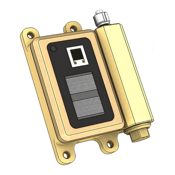
O F T W A R E O M P O N E N T S The Acuity LS device consists of a base and a lid-sensing panel (LSP). The base contains the microcontroller electronics, battery, and interface connector. The base includes a sensor to measure the temperature of the surface to which it is attached. - Page 4 Figure 2. Acuity LS components. For any technical support needs, including software installation and device troubleshooting, please contact support@acuitycorrosion.com. #OMA20241022 Acuity LS Operating Manual Page 4...
-
Page 5: Interface Software And Driver Installation
This section provides instructions for installing the interface software that allows users to configure their Acuity LS devices and download stored data. Software version 5.0 is designed to work with the entire family of Acuity products, provided that the devices have compatible firmware installed, as indicated below. -
Page 6: Interface Software Operation
Establishing Connection To establish connection between an Acuity LS device and the computer: Plug the Acuity LS interface cable (Figure 2) into any of the PC’s available USB ports. The cable’s red/green LEDs will blink, indicating Windows has recognized it. - Page 7 Figure 4. Selection window when multiple devices are found. 6. If no devices are found, a window offering basic troubleshooting guidance will appear (Figure 5). If none of these remedies are successful, please contact Acuity support. Figure 5. Troubleshooting window when no devices are found.
-
Page 8: Operating The Acuity Interface Software
Operating the Acuity interface Software The Acuity interface software main window is a combination of status indications and buttons to perform various commands (Figure 6). This section describes the meaning of each indicator and the details of each command. To help guide a new user through the specific steps of configuring a device and downloading records from it, please see Section 5. - Page 9 Firmware Ver. – Firmware version installed on the device. • Configuration – Indicates whether the Acuity LS device is configured to measure one • galvanic and one free corrosion sensor (Single Galvanic) or two galvanic sensors (Dual Galvanic).
-
Page 10: Checking Device Status
Synchronize Clock – Adjusts Acuity LS device clock to match the PC clock. • NOTE: Please verify accurate local PC time before synchronizing Acuity LS clock. Take Measurement – Immediately takes a measurement, regardless of logging • status, and displays the result on window to verify sensor operation. Measurements taken in this manner will be stored to the device memory. - Page 11 Adding user input descriptions is not required for Acuity LS operation; but may help document test details and device use. When first opening this window, the text values shown are those currently stored in the device.
-
Page 12: Stop Logging
Please refer to Section 6 for details about the file types and their contents. Figure 11. File save window with default file name. User may change the name and folder as desired. #OMA20241022 Acuity LS Operating Manual Page 12... - Page 13 Record Write Faults – Under weak battery conditions, there may not be enough • electrical energy available for the Acuity LS internal memory to successfully complete a record storage operation following a measurement. Normally, the device recognizes this weak battery condition and will skip the record storage operation to avoid a fault, but in certain cases it may still attempt a write that cannot be successfully completed.
-
Page 14: Clear Records
WARNING: After a failed erase records operation, the memory is not properly configured to store any new measurement records. It is critical to perform a successful erase records operation before data logging and storing any new records. Contact Acuity support if battery replacement does not remedy the problem. -
Page 15: Synchronize Clock
PC time is accurate before continuing. Click “OK” to continue. Figure 15. Syncing device and PC times. (left) Device is far out of sync due to power loss (right) Device clock successfully synchronized. #OMA20241022 Acuity LS Operating Manual Page 15... -
Page 16: Take Measurement
RH / Air Temp sensor built into the LSP. For the battery chemistry used in Acuity LS, battery voltage is not a strong indicator of remaining state of charge. It is provided here for information purposes only. -
Page 17: Common Operations
“Exit” to leave the application. 8. Disconnect the interface cable from the device. 9. Replace the interface connector cap. Acuity LS is now collecting data at set measurement interval. Download Records Establish connection to the device (Section 4 - Establishing Connection). -
Page 18: Data File Contents
The file ending in “.acu” is a raw data stream from the device and is only used by the • Acuity product support team to diagnose device operation. The “.csv” file uses comma-separated variable (.csv) formatting that is easily imported into analysis tools like Microsoft Excel. -
Page 19: General Information
#GENERAL INFORMATION Download Date Date and Time that the download occurred Acuity Device Type Specifies the product type (Acuity LS, ES, or CR) Device ID Matches the ID label on the device Single Galvanic: (1) free corrosion, (1) galvanic corrosion... -
Page 20: Downloaded Records
Downloaded Records Following the file header, the downloaded records section contains all the useful information from the device, arranged in columns (Table 3). Table 3. Data file column measurements and descriptions for Acuity LS devices. Column Measurement (Units) Description Number of seconds since midnight Jan 1, 1970 (UTC+0) Unix Time (s) See “Unix Time Conversion”... -
Page 21: Device Maintenance
Highly corroded sensing surfaces may require LSP replacement. CAUTION: Do not immerse the Acuity LS device or flood the filter cap area that houses the relative humidity and temperature sensor with solvent, as this could affect the temporary operation of these sensors or cause permanent damage. - Page 22 3. Orient the LSP so that its two metal pins align with the mating holes in the Acuity LS base (Figure 17). CAUTION: Misalignment or using the wrong orientation of the LSP could result in bent spring contacts and permanent damage to the Acuity LS base and LSP.
-
Page 23: Battery Replacement
When the battery is depleted, it may be replaced by the user in the field using the steps outlined below. NOTE: The standard battery for Acuity LS is the Saft LS17500 Lithium Thionyl Chloride primary cell (non-rechargeable). New batteries should only be sourced from Acuity Corrosion Technology or authorized Saft distributors to avoid counterfeit products. -
Page 24: Device Power Cycle (Restart)
To perform a system restart of the Acuity LS device, remove the battery, wait ten seconds, then reinstall the battery per the instructions above. Performing a system restart does not affect stored data or device settings. -
Page 25: General Specifications
The user can replace the commercially available battery. LSP Replacement The Acuity LS Lid Sensor Panel (LSP) is replaceable by the user. Replacement LSP may be purchased from Acuity Corrosion Technology. Data Storage The device’s internal memory can hold up to 120,000 measurements. - Page 26 Dimensions Figure 19. Acuity LS device dimensions, units in inches. Approximate device weight is 0.75 pounds (340 grams) #OMA20241022 Acuity LS Operating Manual Page 26...
-
Page 27: List Of Acronyms
I S T O F C R O N Y M S Acuity LS Acuity LS Corrosion Monitoring Device Diagnostic file extension Compact Disc Comma-Separated Variable file type Device Identification Number (shown on the device label) Interdigitated Electrode Isopropyl Alcohol...
Need help?
Do you have a question about the LS and is the answer not in the manual?
Questions and answers